
Role
Designer
Fabricator
Team
Shiva Kansagara
Delaney Wong
Dan Klin
Timeline
Mar 2024
Skills
Interaction Design
Graphic Design
Physical Computing
Problem Solving
Fabrication
Digital Fabrication
Tools
Arduino
ProtoPie
TinkerCAD
Adobe Illustrator
Helix Mini Laser Cutter
Soldering Iron
Project Overview
Take apart a device and enhance it with an Arduino.
01
PARTS & SET-UP
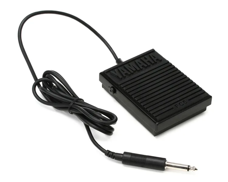
Initial device: Yamaha FC5 Sustain Foot Pedal
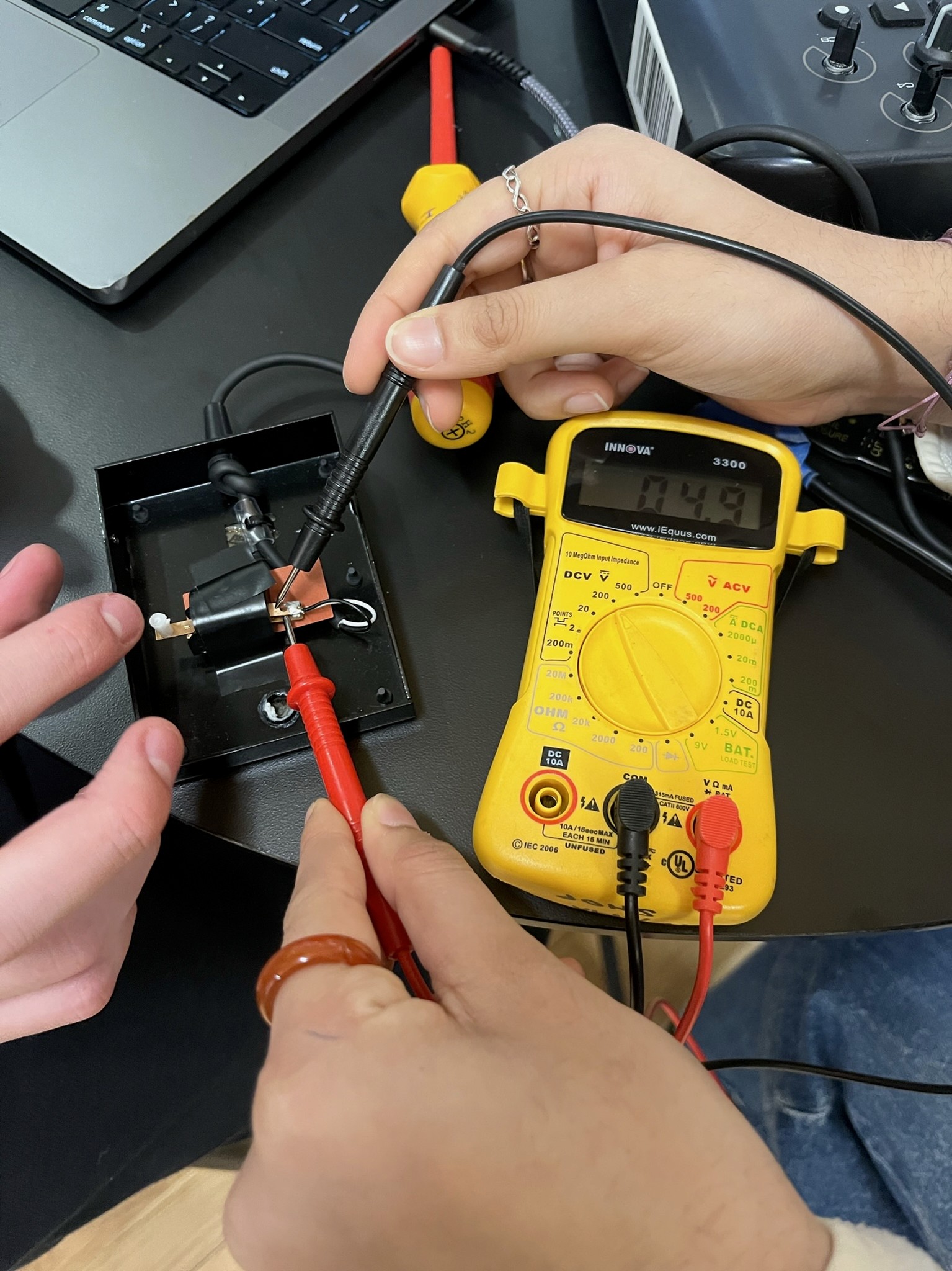
Took the voltage of the pedal when connected to a portable keyboard. Received a 5V signal.
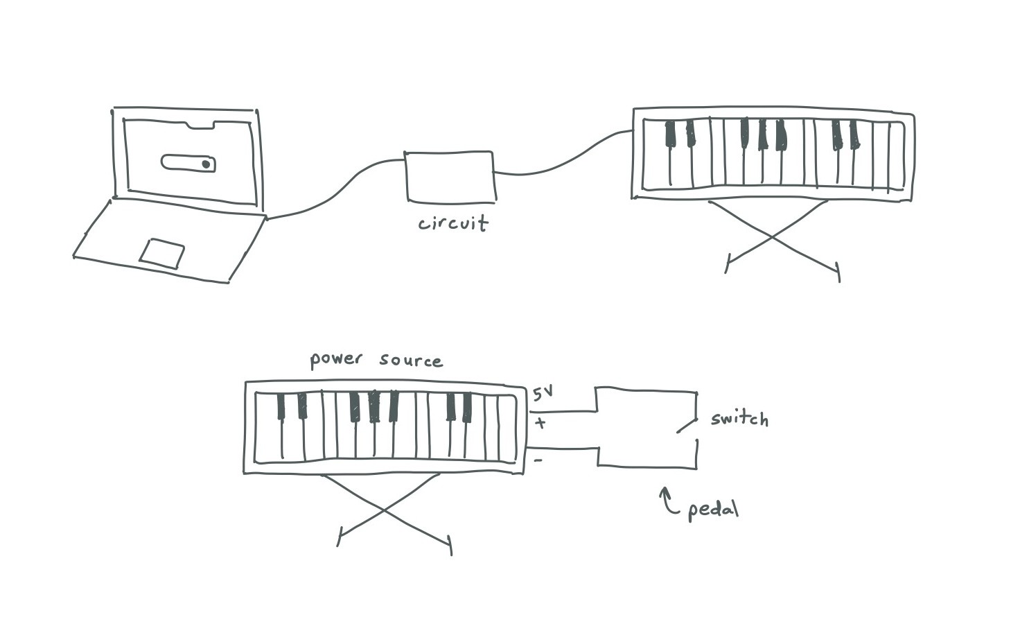
Logic diagram illustrating how the components would interact. Decided we would recreate the sustain pedal from scratch using motors and a digital interface.
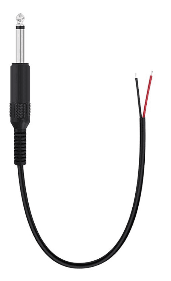
This cable is the part that remains consistent between the Yamaha pedal and our newly designed pedal.
02
PROTOPIE
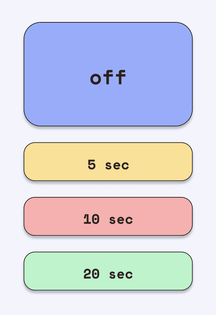
Delaney and I used Figma to create the assets for the ProtoPie interface.
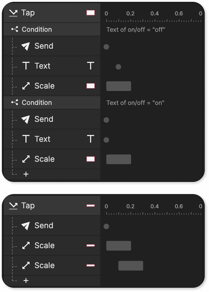
Then, I brought the design into ProtoPie and added the triggers. One trigger was for the on/off button: when pressed, the "off" should read "one" and vice versa. There was also a trigger for scale on all buttons to indicate that it was pressed.

case 0: off

case 1: on

case 5: five seconds on
While I did this, Delaney was researching how to connect the data between ProtoPie and Arduino. She found that the trigger “send” would allow us to add a “toggle,” or a value for what we want the state change to be, when pressed.
03
ARDUINO & CONNECTION
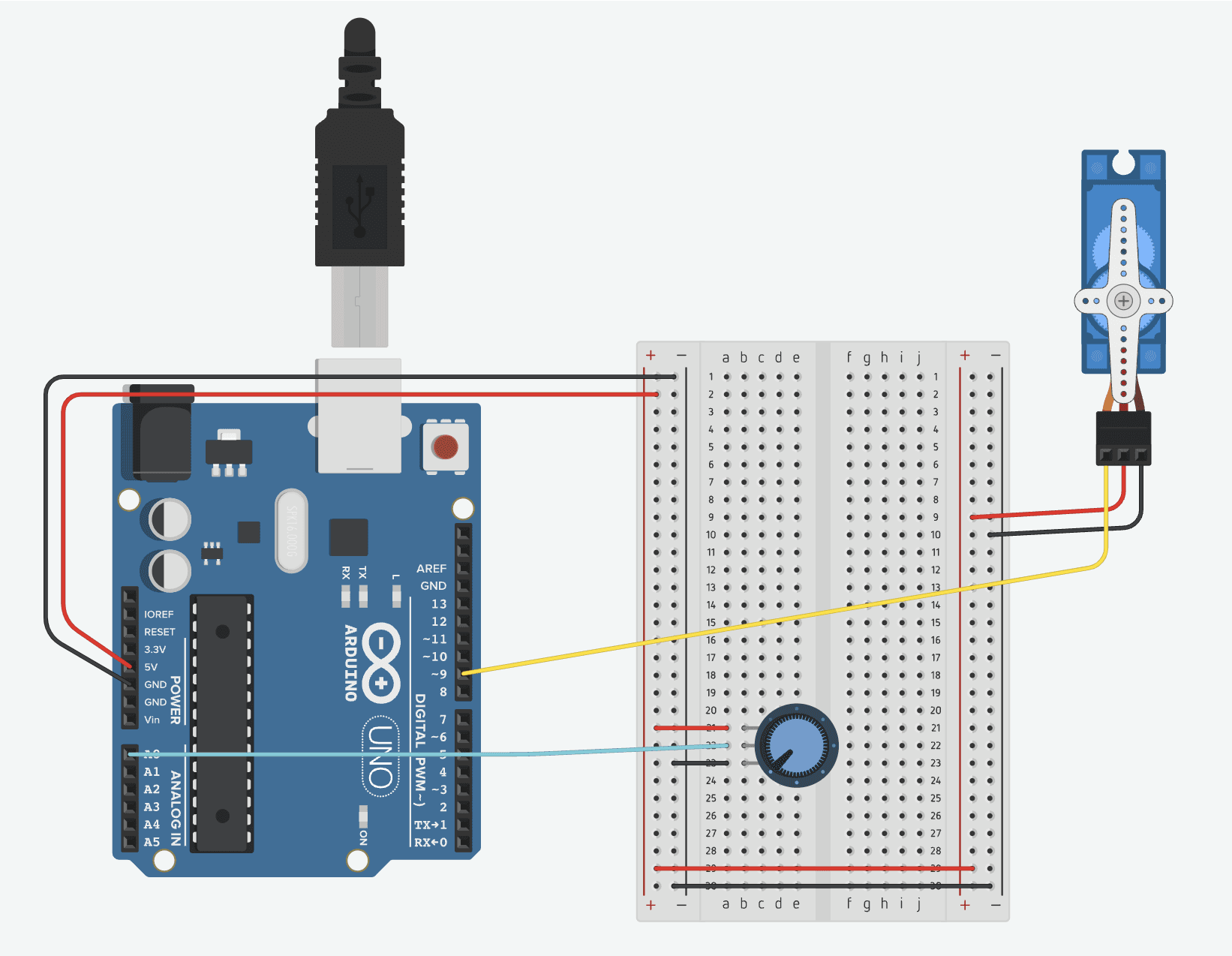
In the meantime, Dan was building out the circuit that would use Arduino to control the Servo. He based his design on my TinkerCAD sketch above. After building that initial circuit, he removed the potentiometer and added serial communication. Serial communication allows the data to be sent and received (ie: to ProtoPie). This new code allows the Servo turn a certain number of seconds depending on the state. For example, state 5 would allow the servo to turn for 5000 milliseconds, or 5 seconds. Code posted to my Github.
Now it was time to connect the ProtoPie to Arduino via ProtoPie Connect. This took a while to figure out because we were missing the crucial information of running the Arduino plugin on ProtoPie Connect. Once we figured this out, the potentiometer was working.
04
FABRICATION ASSEMBLY
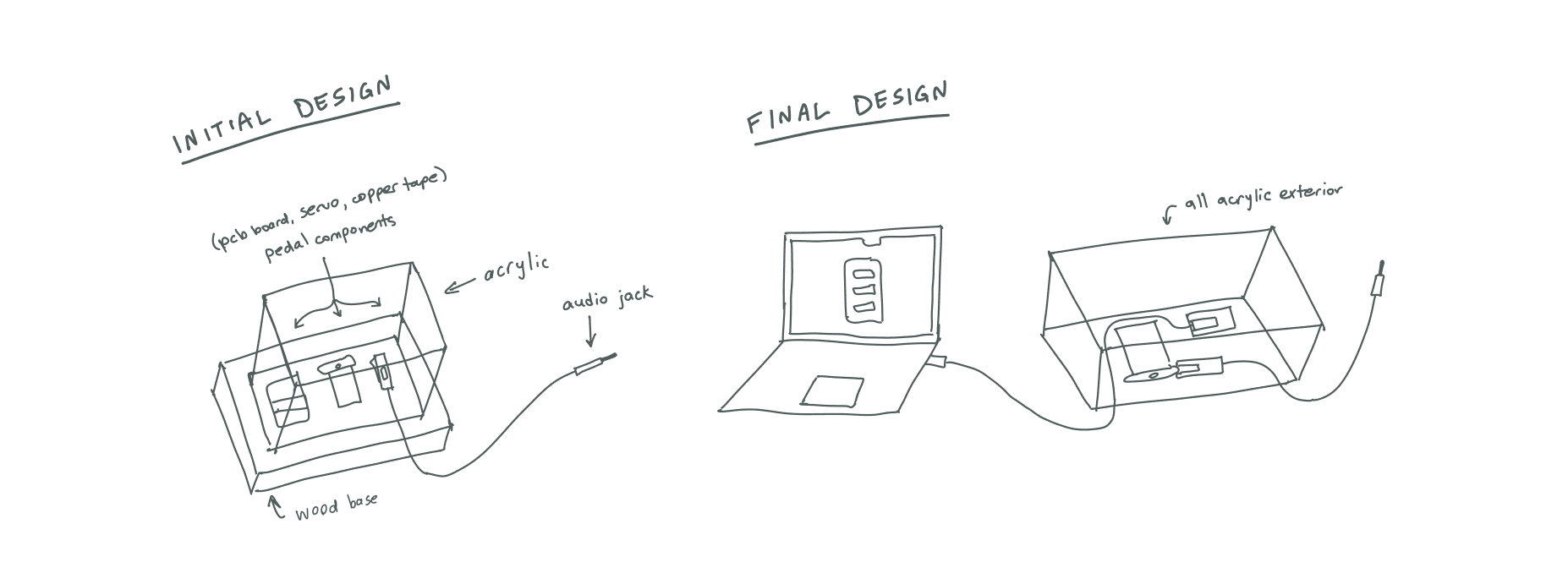
The next day we began creating the physical enclosure. Initially, we were going to use wood and acrylic materials, but we decided to just use acrylic for simplicity.
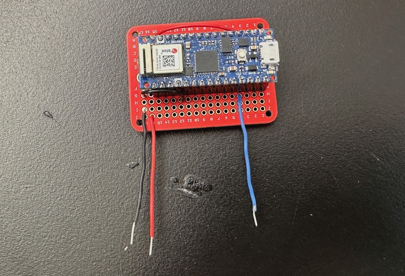
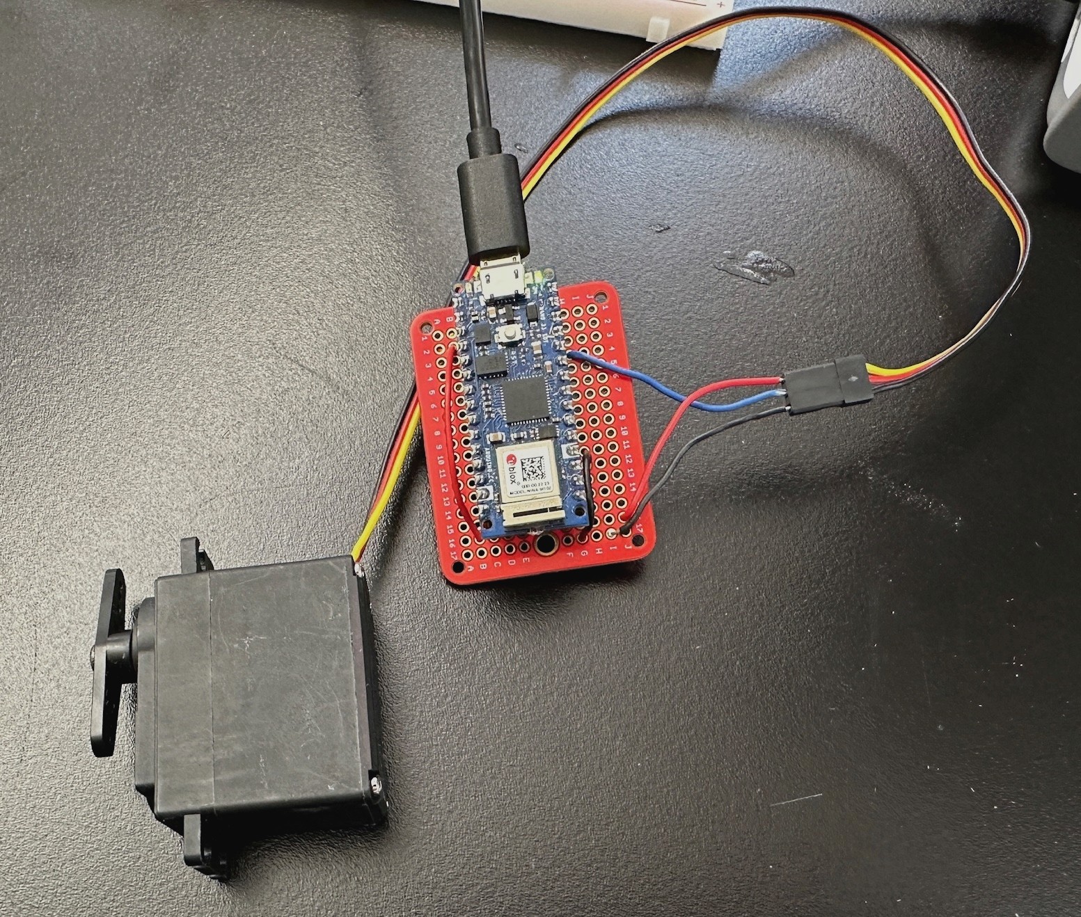
Delaney transferred the circuit from a breadboard to a mini PCB board and soldered the wires to it. One obstacle we ran into with this was not knowing how to connect power and ground (as there were no labels like on the breadboard). This was our first time working with a PCB board.
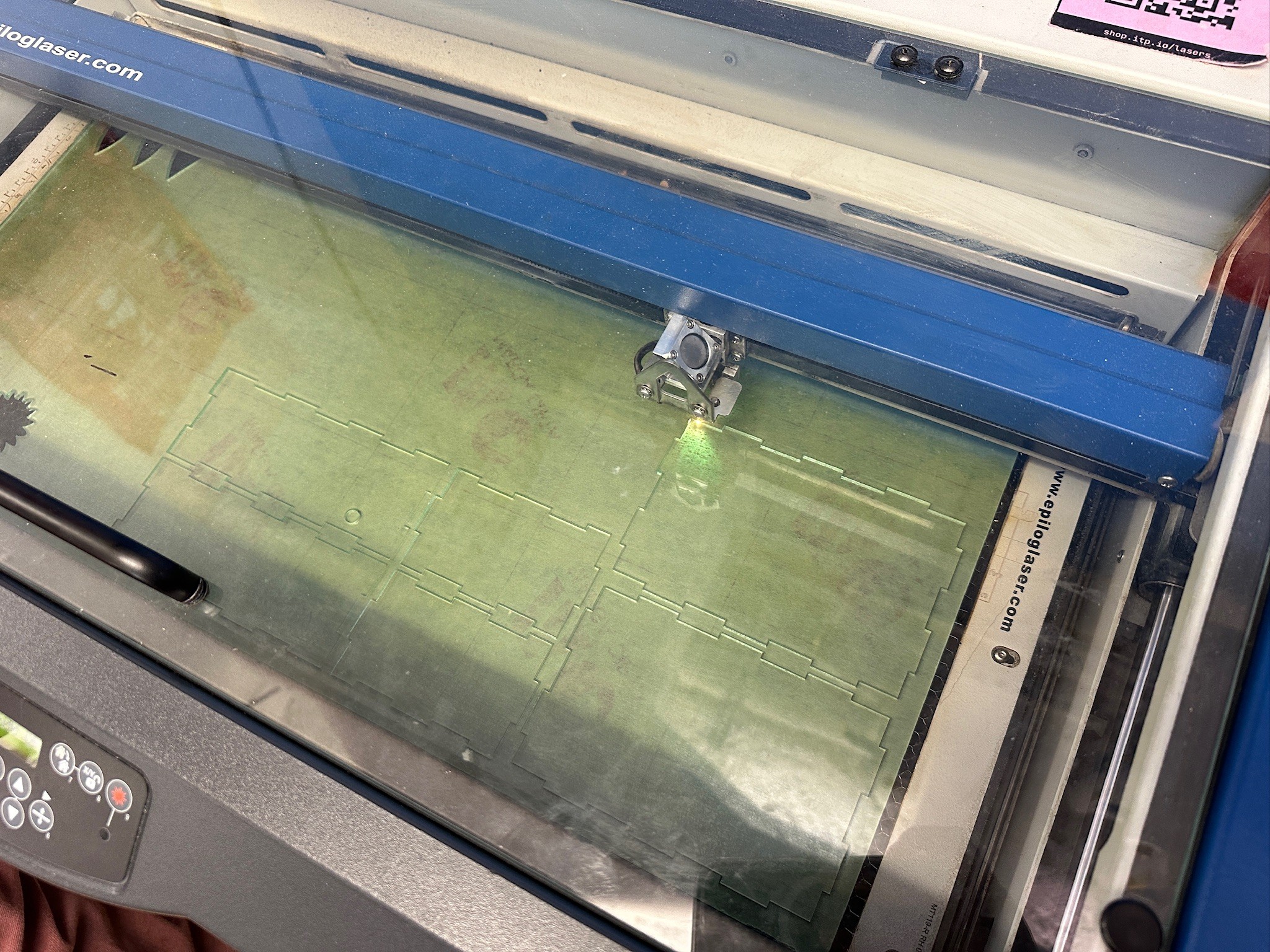
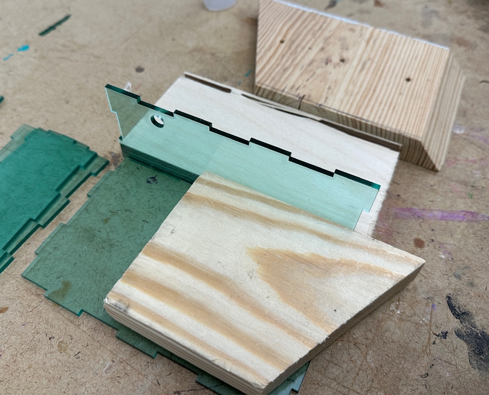
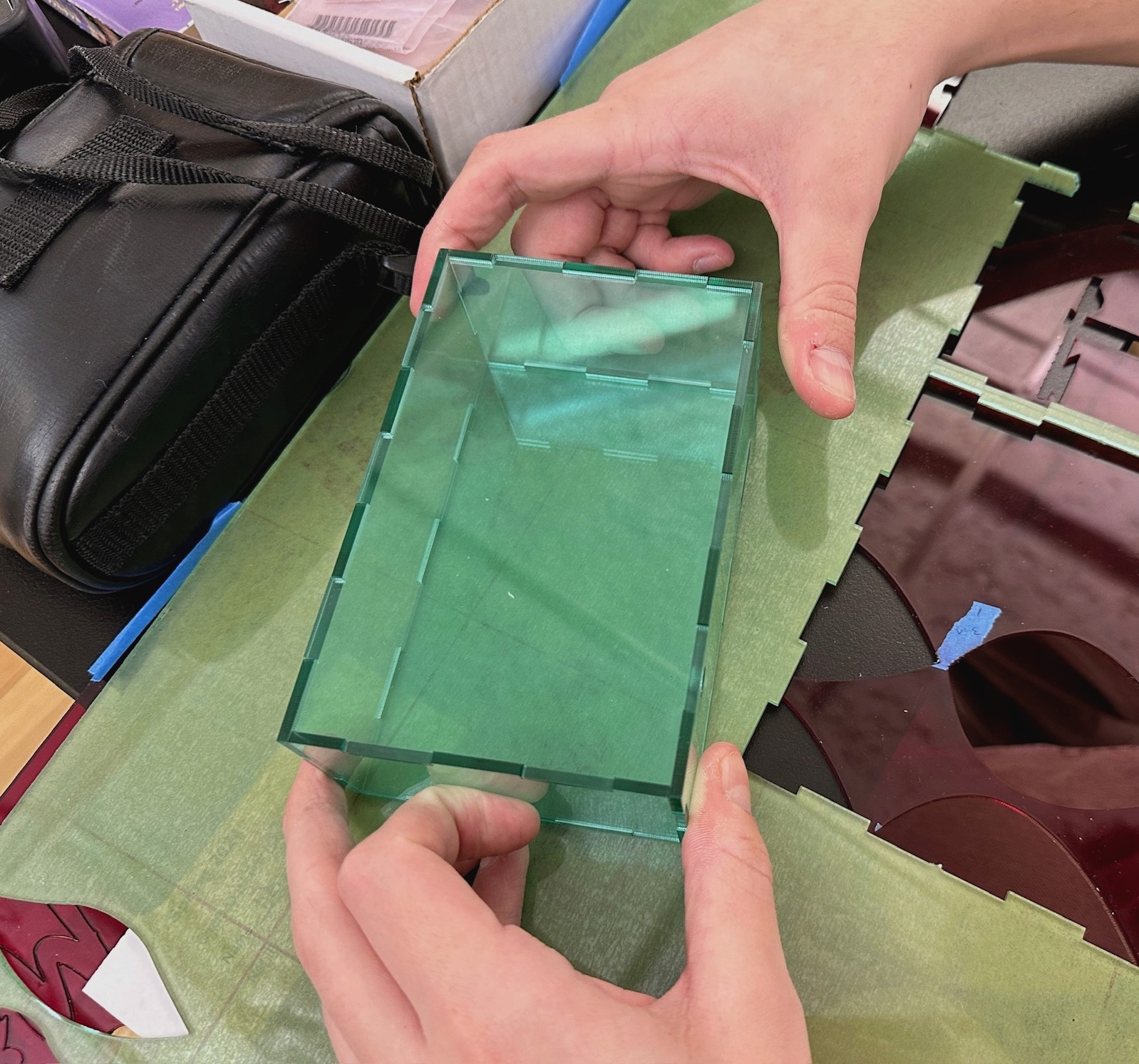
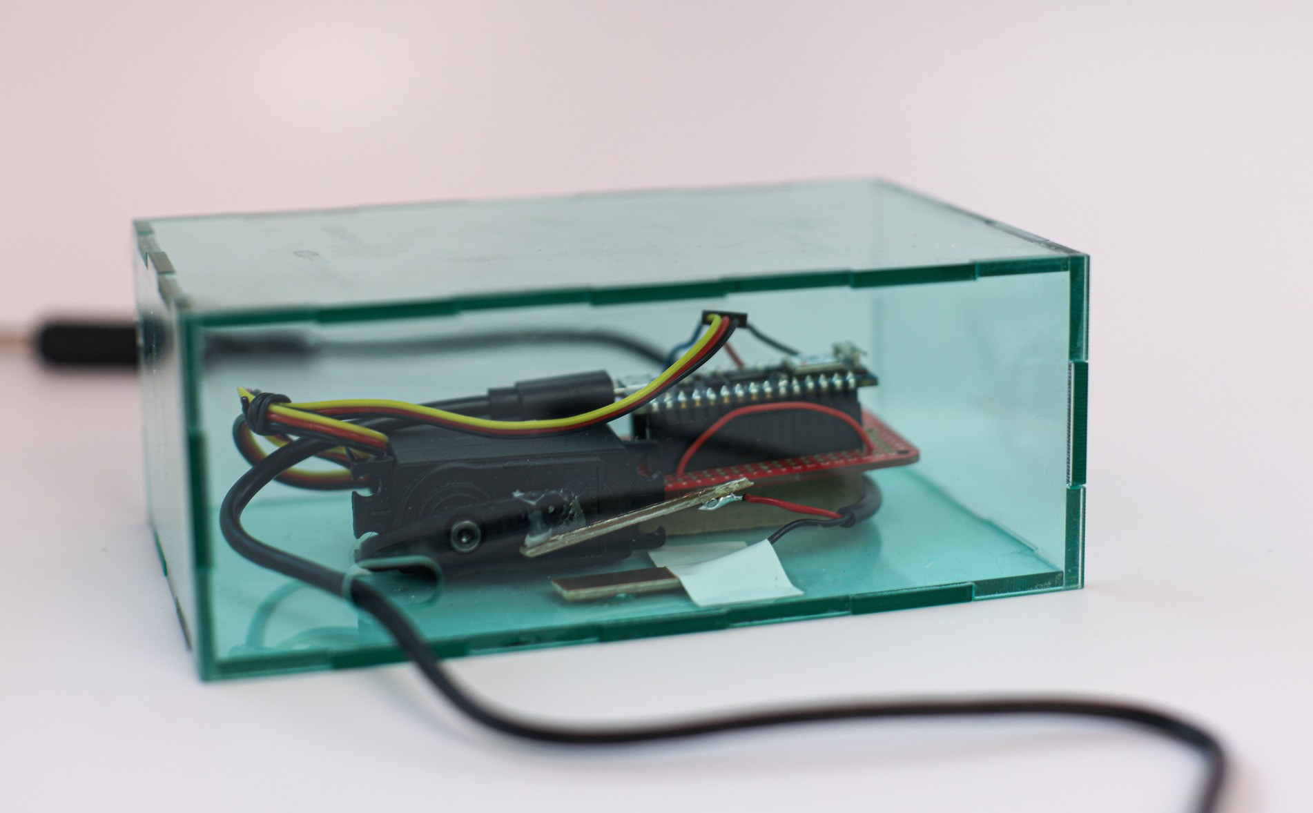
Dan and I began assembling the acrylic enclosure where all the components would live. After laser cutting and assembling the box with weldon, we realized we forgot to include a hole that allows the wire to connect the Arduino with the computer. We ripped off one side of the box and stuck it back in the laser cutter to add this second hole.
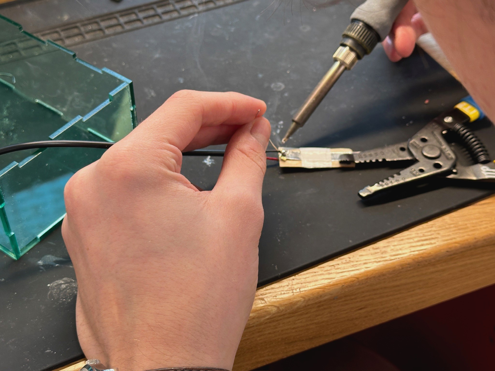
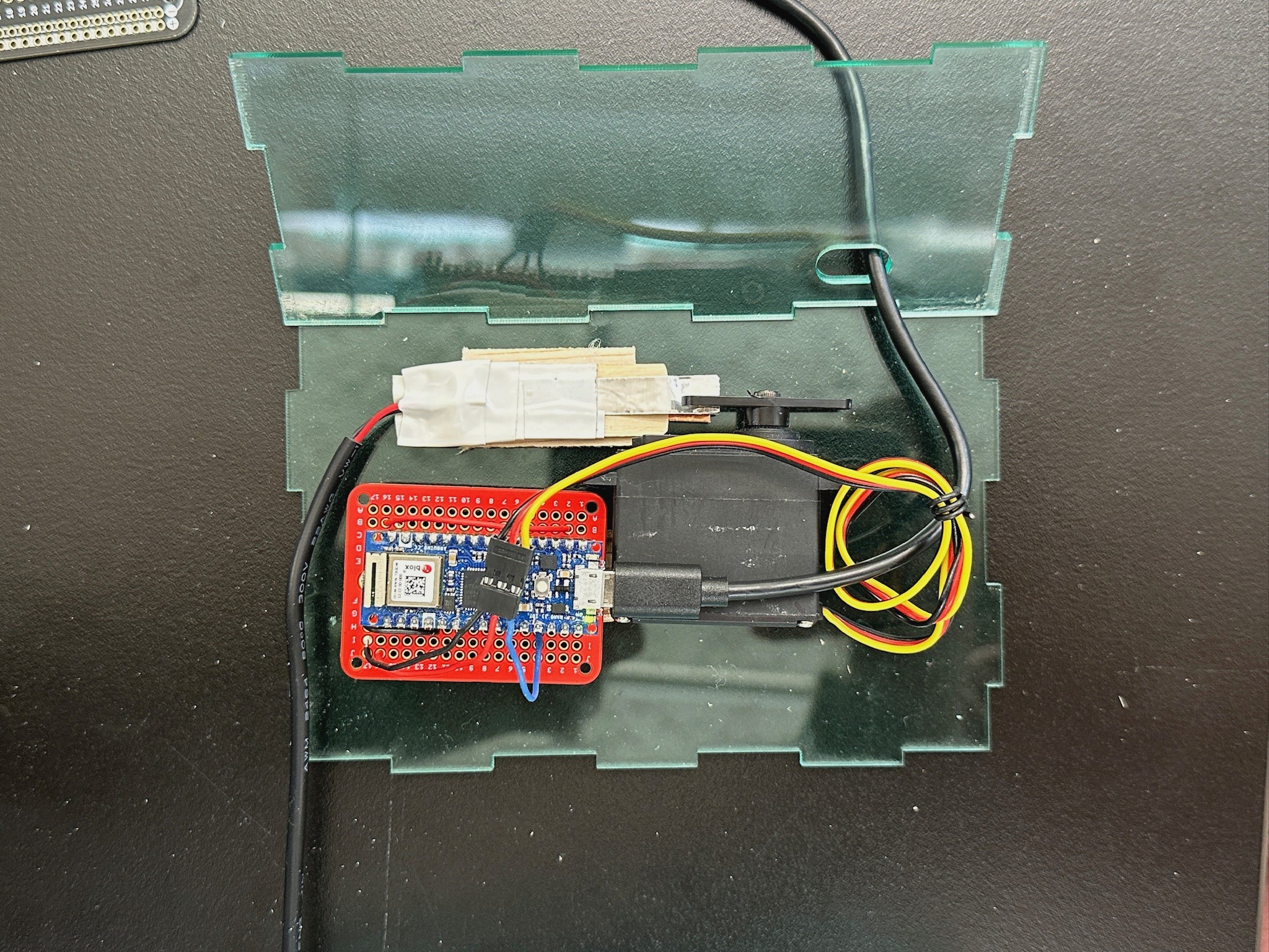
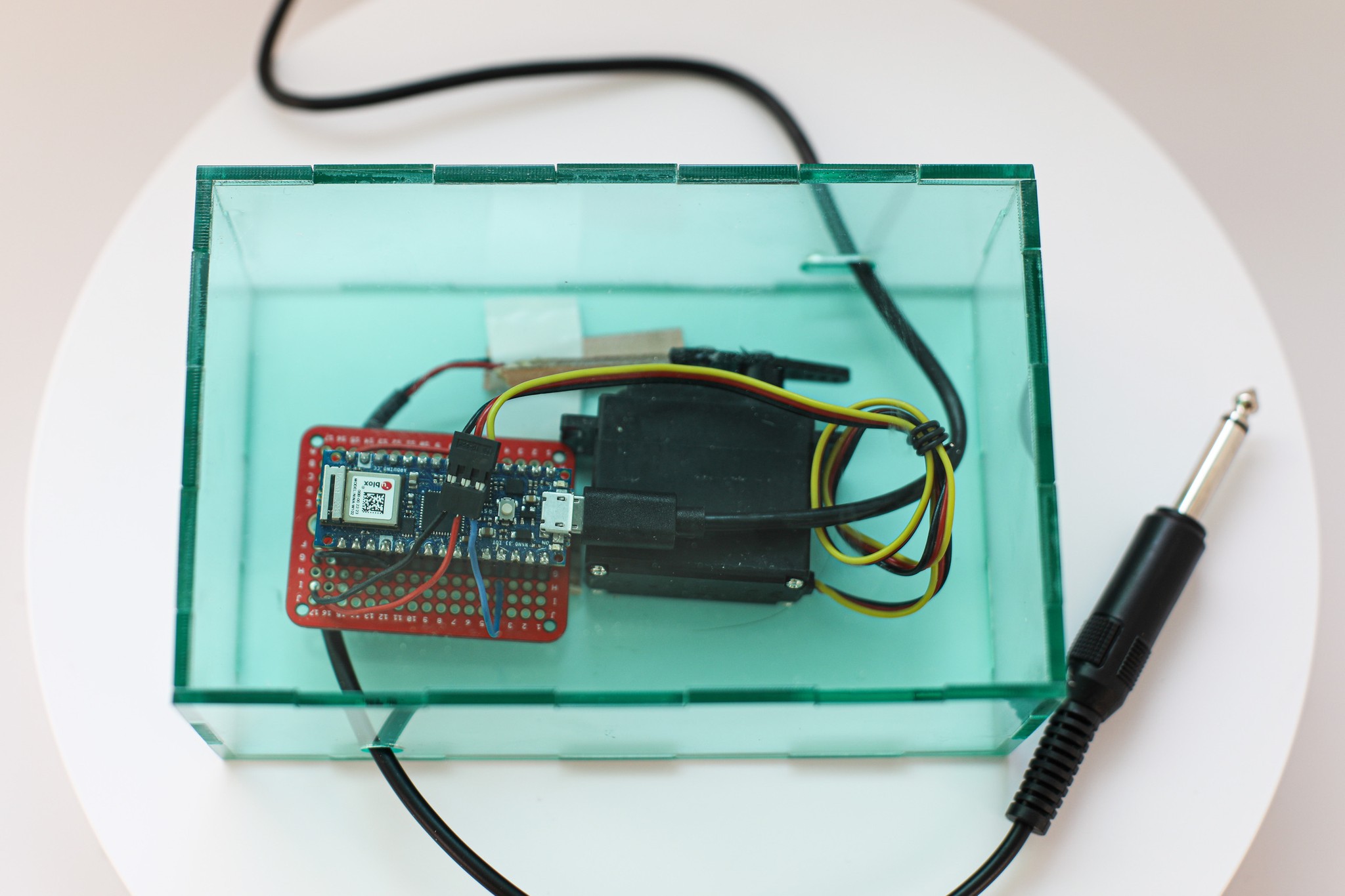
Dan then soldered the two wires of the keyboard cable to two pieces of copper paper, which are responsible for closing the circuit. The photo on the right is what our project looked like after managing the cables and rearranging the components to fit snuggly into the enclosure.
When we tested the device by plugging the cable into a keyboard, we found that when the two copper pieces touch, they aren’t holding a sustain. After playing around with it more, we found that pressure is what works best for this. We had about ten variations of using the copper paper, but it wasn’t until we found copper board and tested it that the sustain was able to be held by just the Servo movement.
05
FINISHED PRODUCT
06
FEEDBACK
