Programmer
Designer
Fabricator
Shiva Kansagara
Delaney Wong
Cody Chu
Maya Pollock
Blair Simmons
Sam Heckle
Apr 2024 - May 2024
Interaction Design
Graphic Design
Physical Computing
Problem Solving
Motion Design
Storytelling
Fabrication
Digital Fabrication
Three.js
Node.js
Arduino
Fusion360
Adobe Illustrator
UltiMaker Cura
Shopbot CNC
Helix Mini Laser Cutter
Epilog Pro Laser Cutter
Vibrant Matter, as described by Jane Bennett, is the inherent liveliness and active presence formed in all forms of matter (living and nonliving). As we move through our day to day lives, many of us dismiss these nuances of our world that are not immediately present.
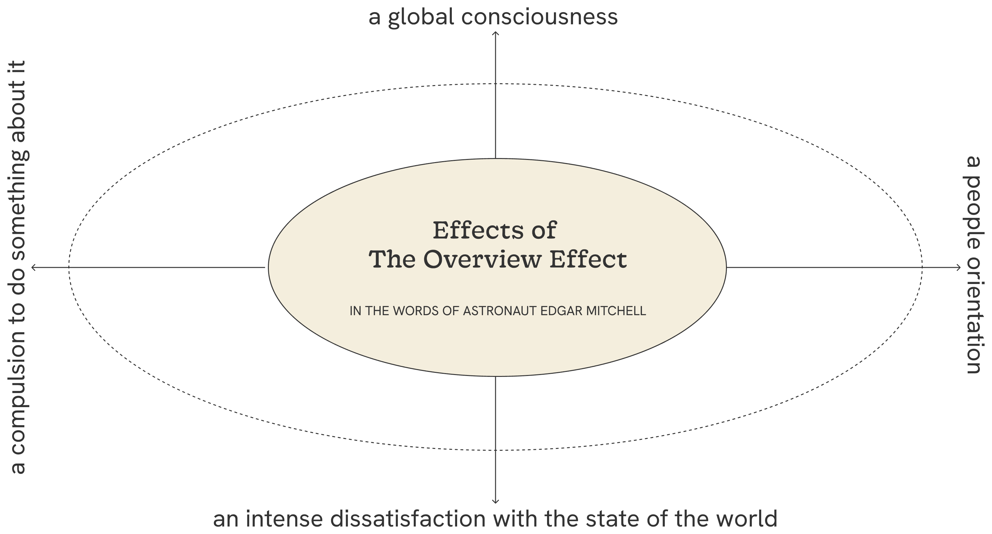
is a shift in perspective when you view the earth from space
causing a sense of wonder and interconnectedness with planet earth and its inhabitants
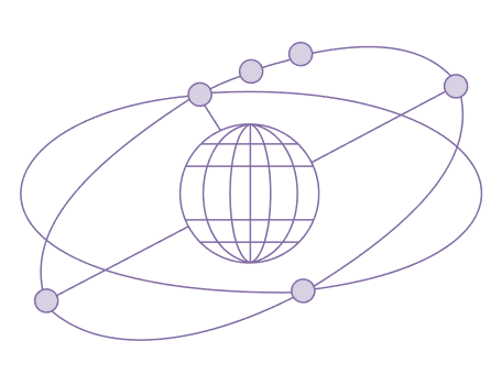
allowing us to realize all of the things, or matter, that make up our Earth have some sort of “potential for influence within the world.”
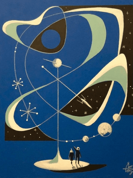
Inspired by retro illustrations and imaginations of space travel.
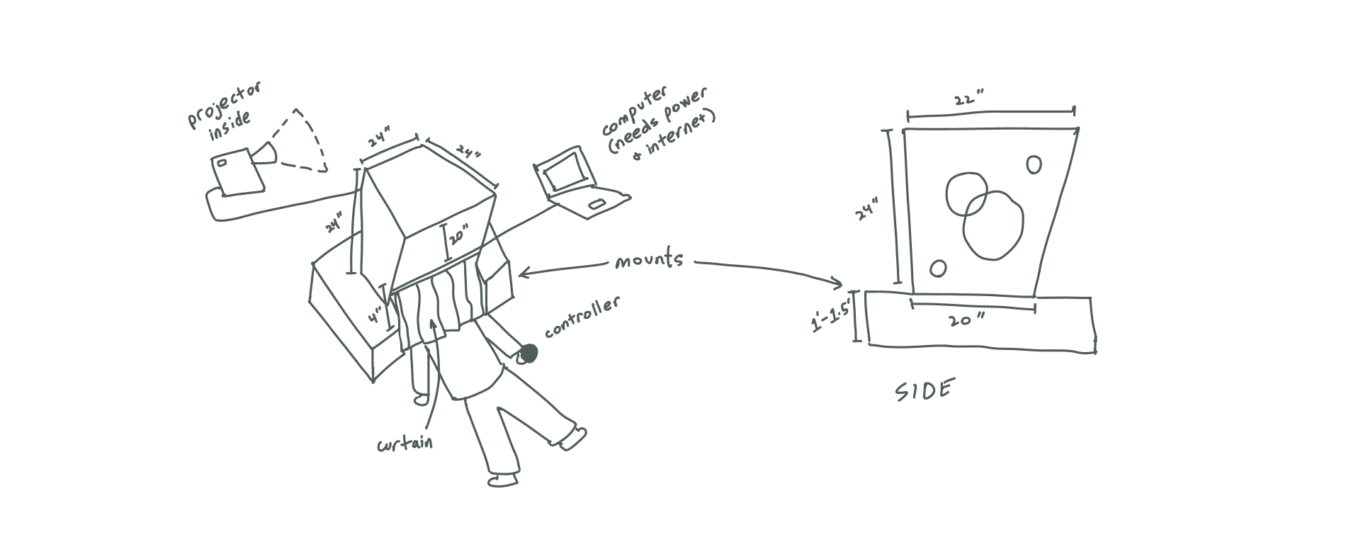
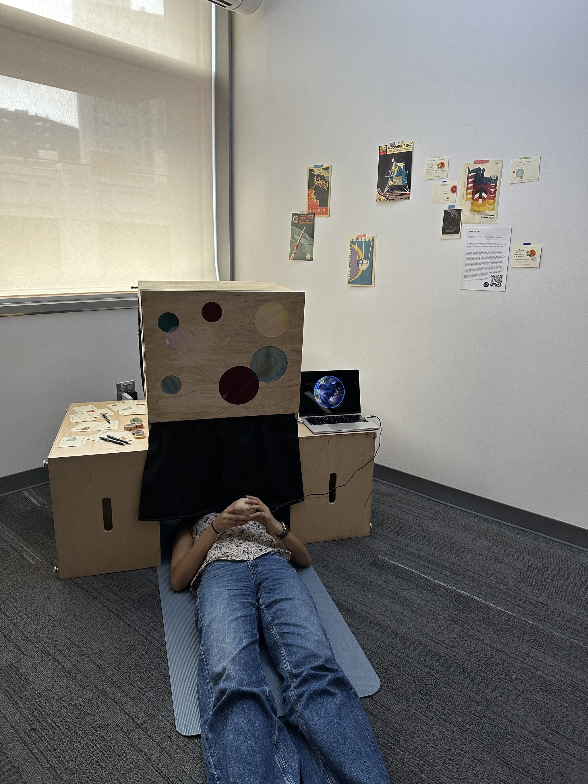
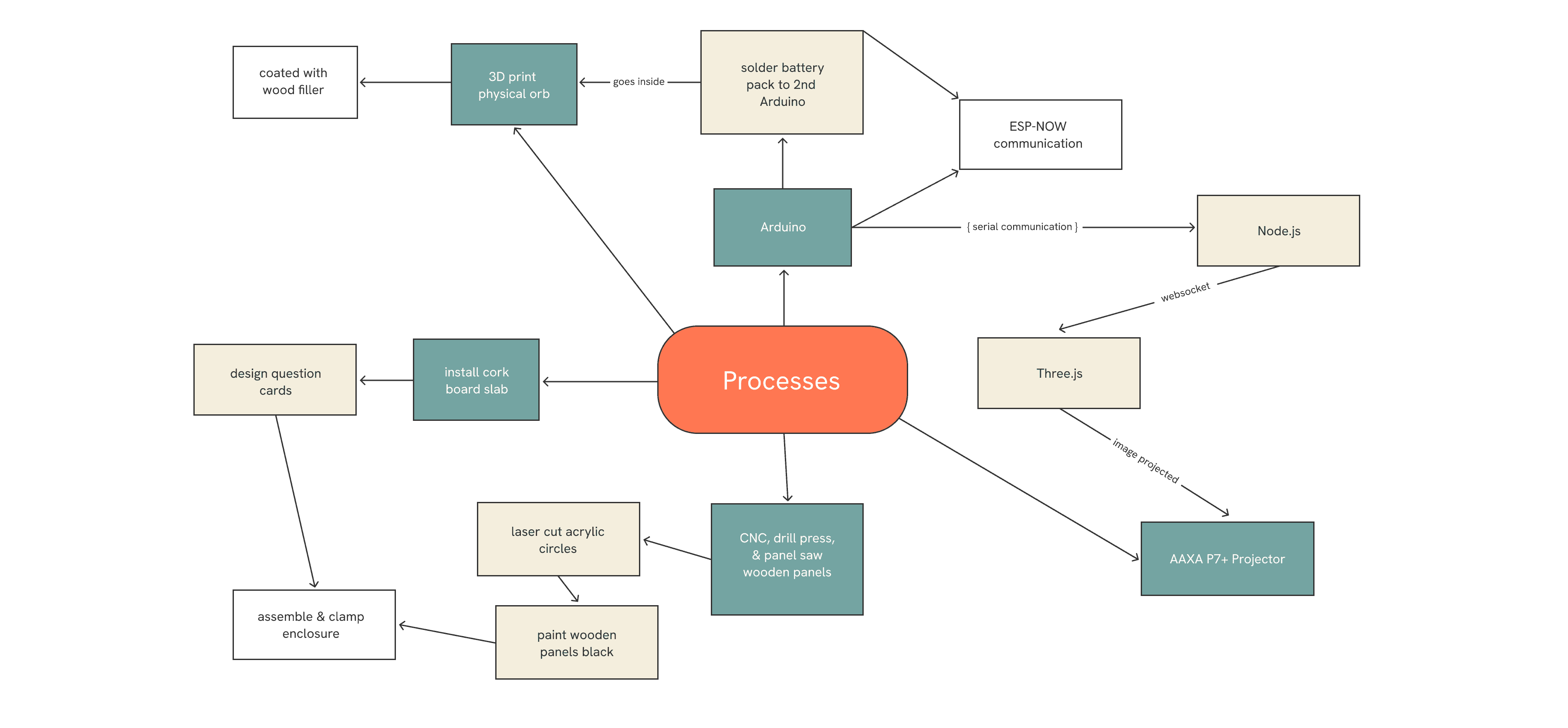
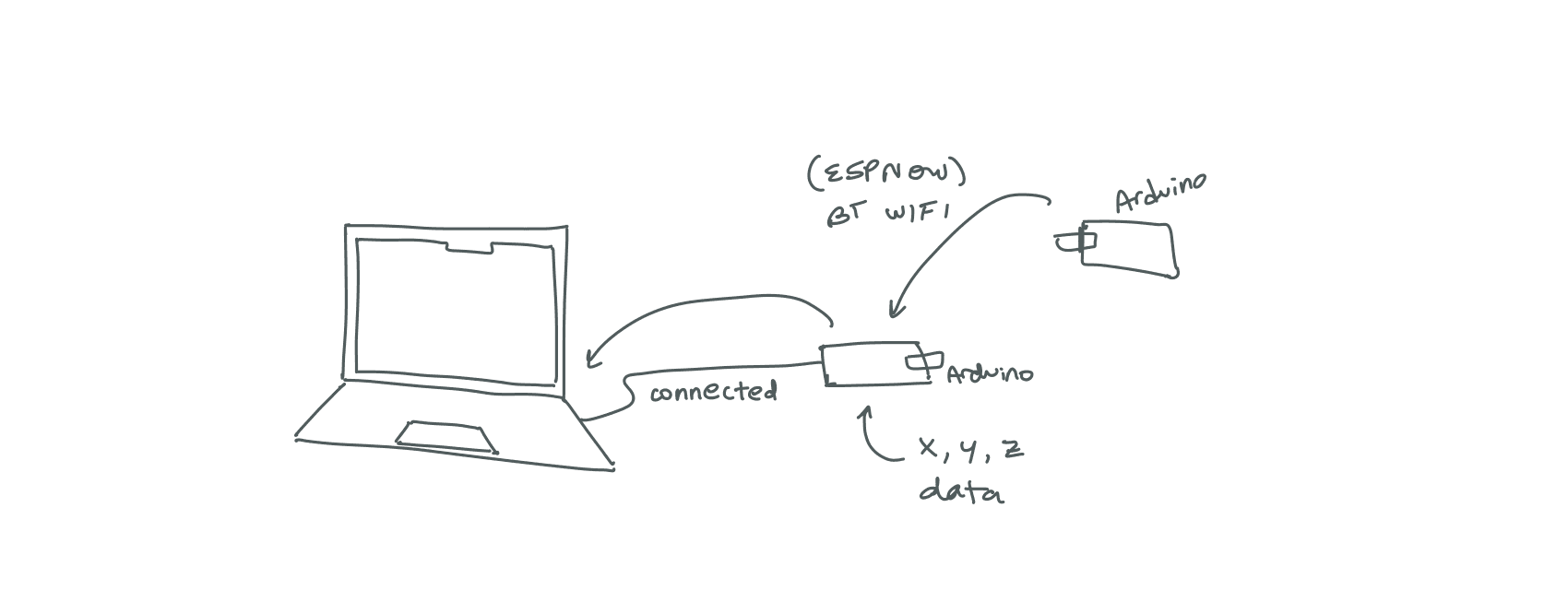
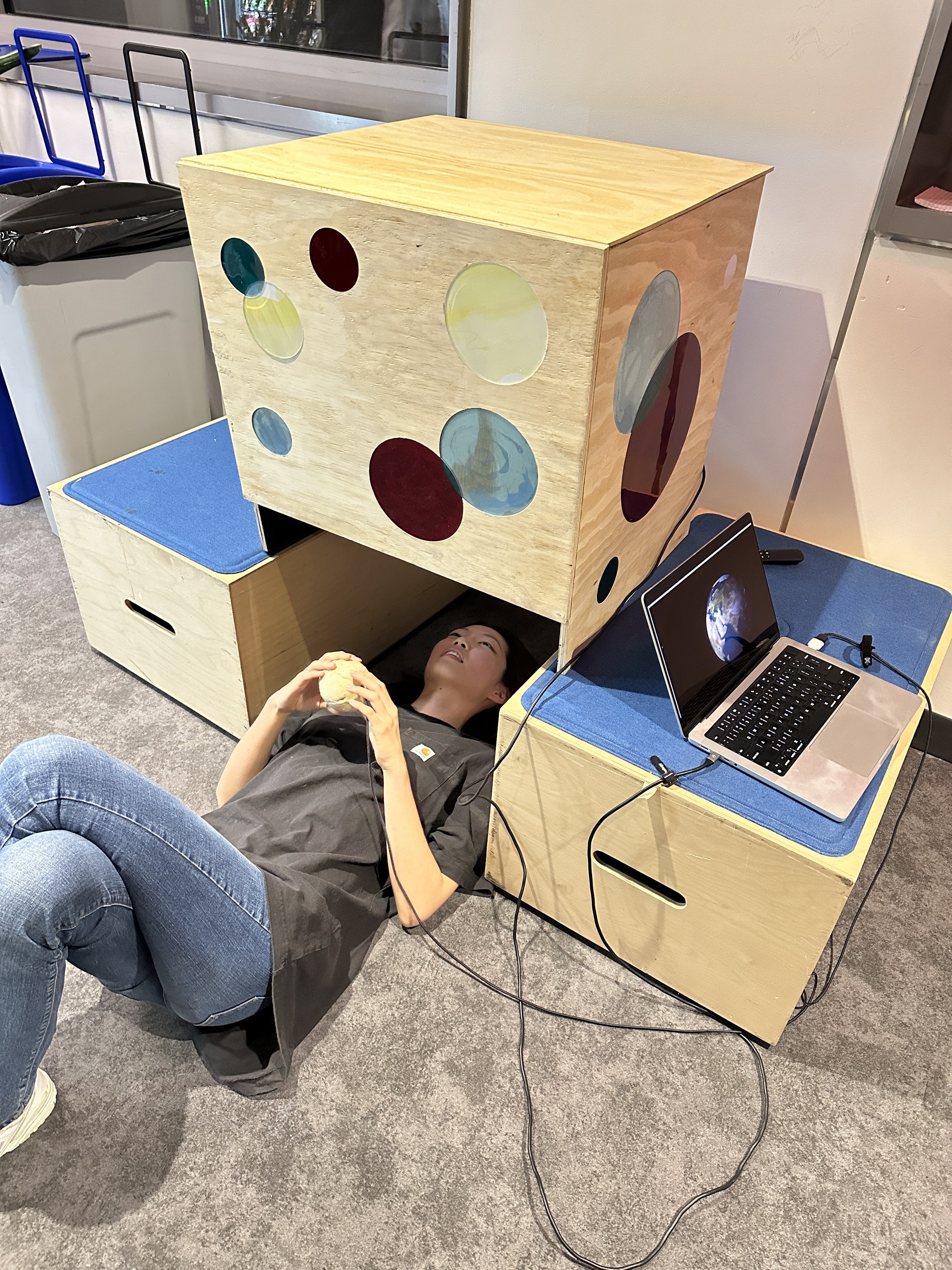
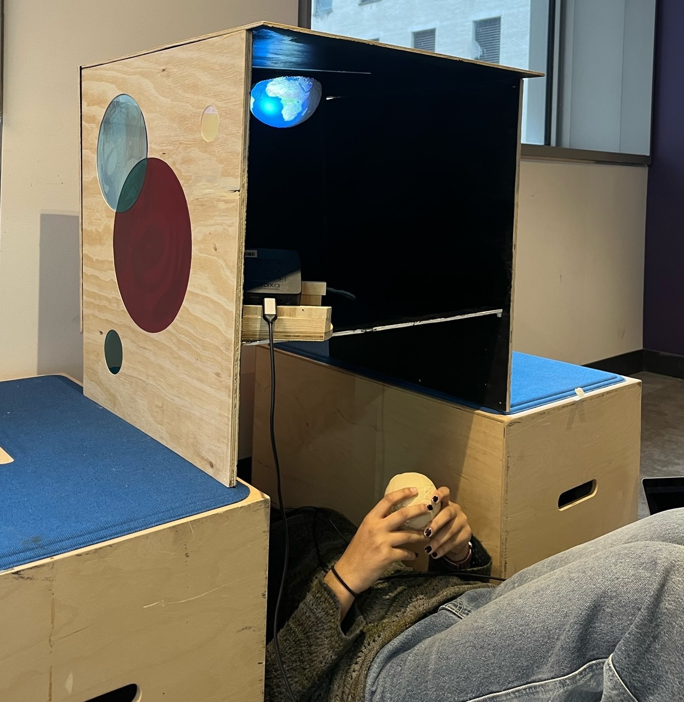
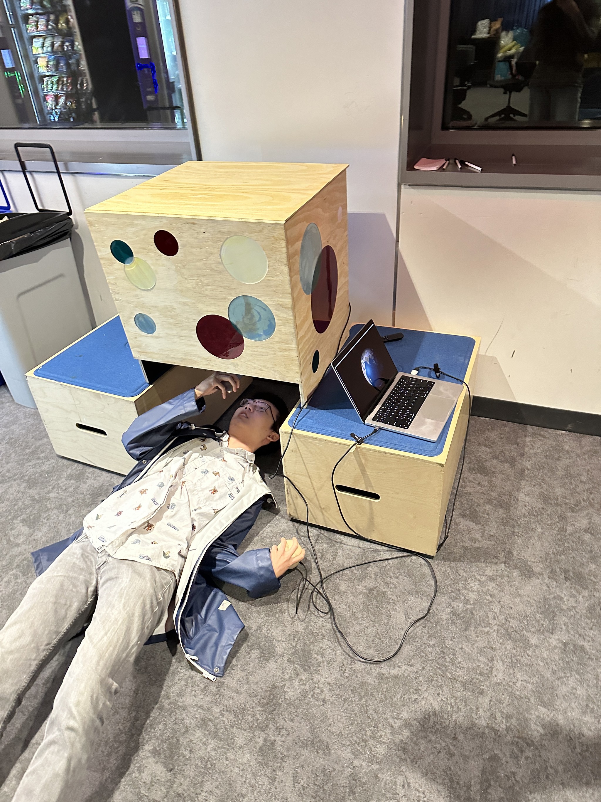
A 3D printed globe controller containing an Arduino Nano IOT33 reports gyroscope data via BLE connection to another Arduino that is connected to a laptop. When the user spins the controller, the enclosed Arduino’s location information is relayed to the laptop via serial communication and is used to rotate a programmed Three.js model of the Earth according to the user’s movement. The Earth model is projected onto a dome shape using a projector that is connected to the laptop’s display. The installation housing is constructed out of plywood and decorated with acrylic panels. Canvas curtains block out remaining light and allow easy access into the installation.
Note: We consulted with NYU Ability Project (a research space dedicated to exploring the intersection of disability and technology) on accessible alternatives for individuals unable to get down on the ground to view our project. Due to time constraints, implementing these alternatives was not feasible at the time. However, we remain committed to prioritizing inclusivity and accessibility in our work and will continue to explore solutions that make our projects more universally accessible.
The act of compelling users to physically get down on the floor to look up at the Earth is meant to be humbling, emphasizing Earth's sheer magnitude against our inherent smallness. For that reason, we have a responsibility to create impactful change as integral parts of a greater whole.
Send the gyroscope data of the Arduino to a Three.js model using serial communications. Then, integrate Node.js to view the Three.js model on the web or through a localhost.
Step 1:
Get gyroscope data (x-, y-, z-coordinates) from Arduino
and send it to the Serial Monitor so that the Node.js program can parse and utilize the gyroscope data. I utilized a template provided by the Arduino library to send this data.
Step 2:
Send gyroscope data from Arduino Serial Monitor to VSCode Serial Monitor via Node.js and SerialPort.
I wrote the basics of a Node.js file based on code by ITP’s very own Tom Igoe. After spending hours trying to debug and ensuring that our code looked identical to the example, we were still unable to get the Serial connection working. Professor Sam Heckle was able to offer help, and we found that the issue stemmed from inconsistencies with the Serial Port library and version originally installed. At last, the Serial Monitors were communicating!
Step 3:
Use gyroscope data from VSCode Serial Monitor to connect Arduino to Three.js model.
The video explained how to connect gyroscope Arduino data to Three.js models. Through the power of YouTube CC captions, MonkeyWit’s Spanish was translated to English clarity. MonkeyWit utilizes websocket in order to connect Three.js (server) to Node.js (client). I used a simple sphere geometry to simulate the Earth we would soon incorporate. Debugging this to fit our own code warranted many long nights. But, after one minuscule change to a line of code regarding websocket, the stars aligned and our gyroscope displayed on the server as the model moved in synchronous –– well, almost. The model was laggy, so our next step was to add styling.
Step 4:
Style and texture Three.js model.
I followed the beginning part of Robot Bobby’s tutorial on creating an Earth with Three.js, which took us from the green mess above to the smoother yellow mess right here.
Step 4.5:
After following Robot Bobby’s tutorial even further, I created this. It has some texturing, but is still very finicky and sensitive.
Step 5:
Implement smoothing and linear interpolation functions.
A smoothing function is a way to parse incoming data. It takes repetitive or patterned data and calculates the average of those values over a certain domain, capturing the most important data. We adapted this code found on the Arduino docs.
Linear interpolation (lerp) is “estimating the value of a point between two given points in a data set” (study.com). On a graph, this function would create new data points, thus curves, amongst a set of discrete points. In the context of this project, it creates a smoother animation by connecting the points that were generated by the smoothing function. Our lerp factor is 0.01, which defines the range that these new data points will be created between.
Step 6:
Fix rotation so Three.js model can fully rotate 360 degrees.
Sam explained that the high and low data values that were being sent from the gyroscope did not align with the 0 to 360 degrees of a full sphere rotation. In order to translate the Arduino values to degree values, we used a mapping function. The equation is:

We found that the start1 and stop1 of the x rotation is 0 to 150. Since we are mapping to 360, the start2 and stop2 is 0 and 2pi. We plugged these values into the equation above. The next steps were to repeat for the y and z values if necessary.
Step 7:
Implementing a cordless interaction between the Arduino and Three.js animation.
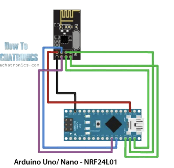
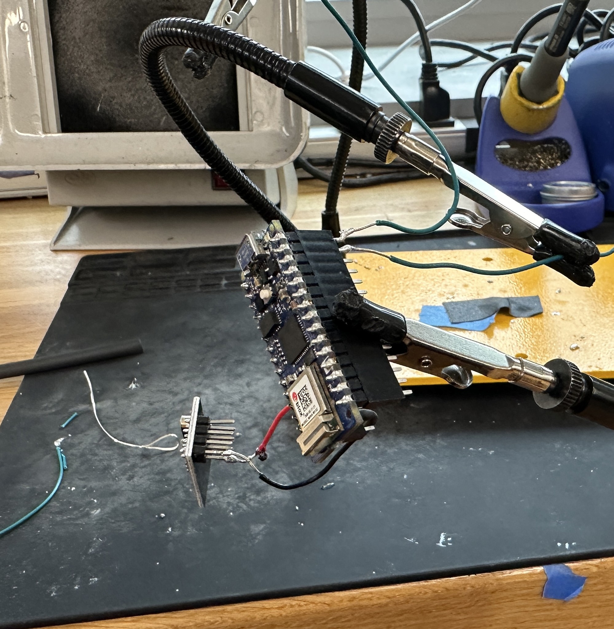
We used the nRF24L01 part, which allows for bluetooth connection and data to be sent between two Arduinos when connected. Each Arduino would have one RF24 – necessitating for our project to consist of 2 Arduinos and 2 RF24s. We found that one would be a transmitter (sending data) and one would be a receiver (receiving data) in order to work in conjunction with Arduino IOT 33s. This website by How To Mechanics outlined the many steps we needed to take.
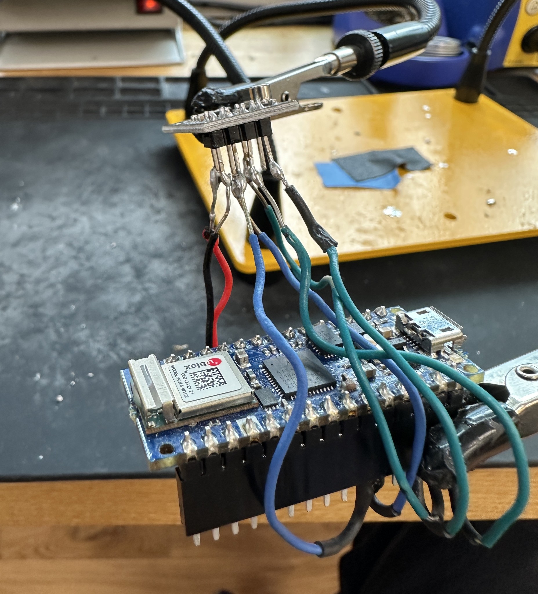
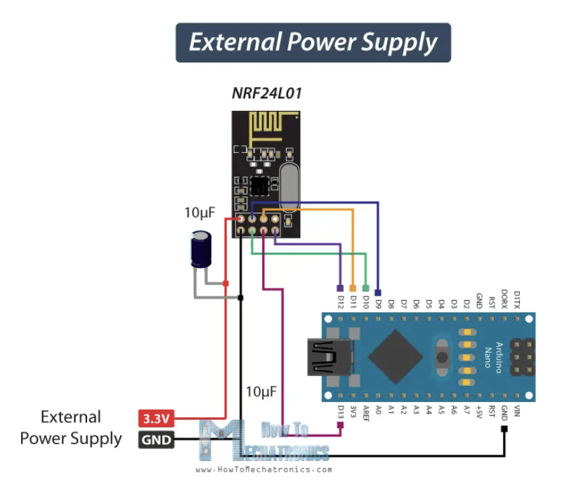
They provided an image of the circuit we would need to assemble, including the Arduino and RF24 (image 1). Since we wanted our interaction to be wireless, we planned to attach our Arduino circuit to a battery pack, which would include two 1.5 volt AAA batteries. The diagram (image 3), also provided on the website, would allow us to successfully attach an external power source to the circuit, or so we thought… We went ahead and soldered the Arduino, RF24 part, and (for one of the circuits) a battery pack (image 4). After uploading the code and printing debug statements, we found that the data was being sent according to the transmitter, but the receiver could not read it. Ultimately, we could not get this bluetooth connection to work given the time constraints and time already expended on this matter.
Step 8:
Styling the Three.js model to look more presentable.
This means finding clear and high-quality textures, adding glows and lighting, and touching up the borders of the code (ie: no margins or coordinates). In order to complete this step, we followed Franky Hung’s tutorial on how to model an Earth in Three.js.
Prepare the files and toolpaths that are needed to build the enclosure.
Acrylic
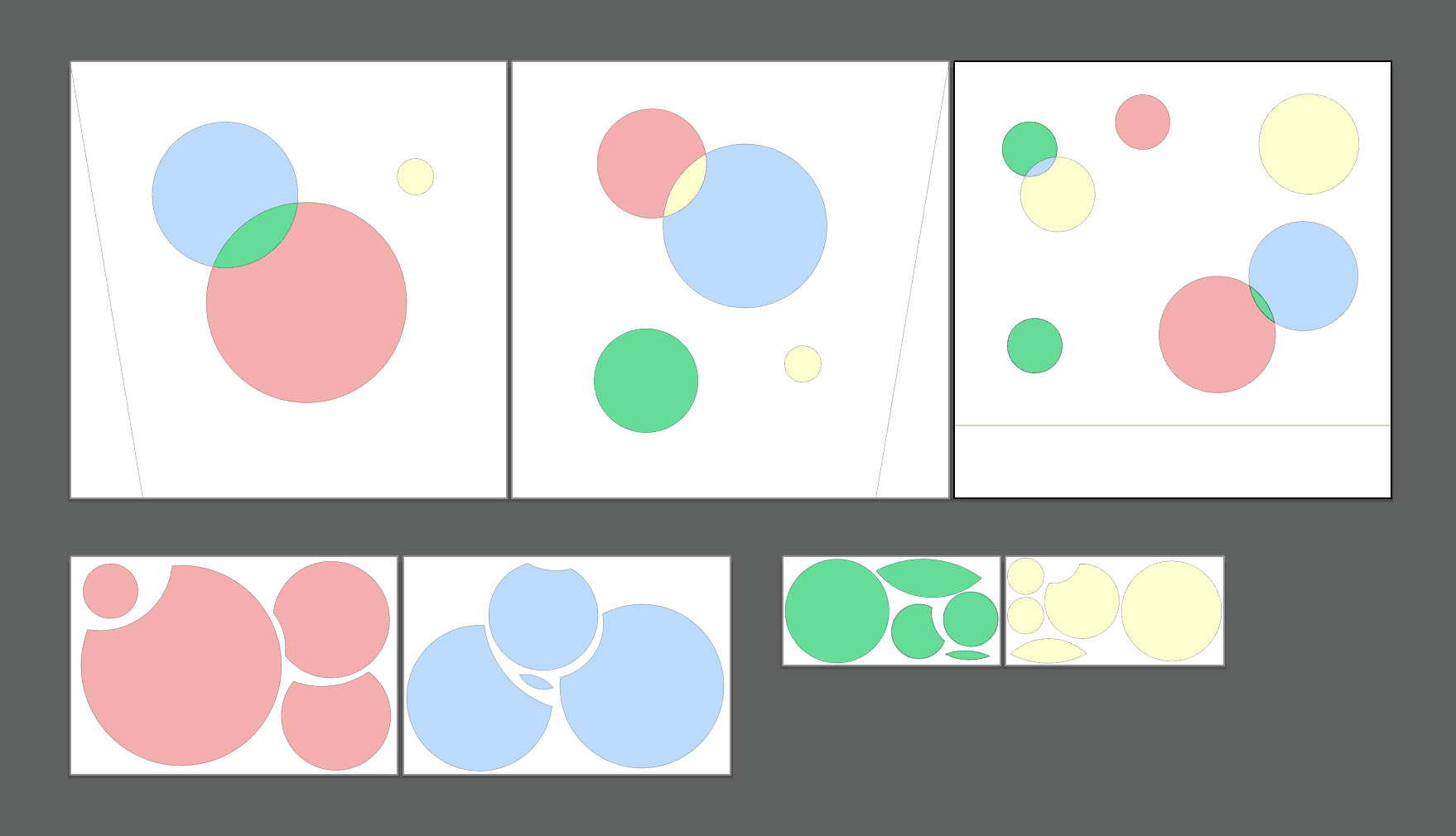
In Illustrator, Delaney designed the circle shapes that would be laser cut out of acrylic on the Mini Helix Laser Cutter and Epilog Pro Laser Cutter.
Wood
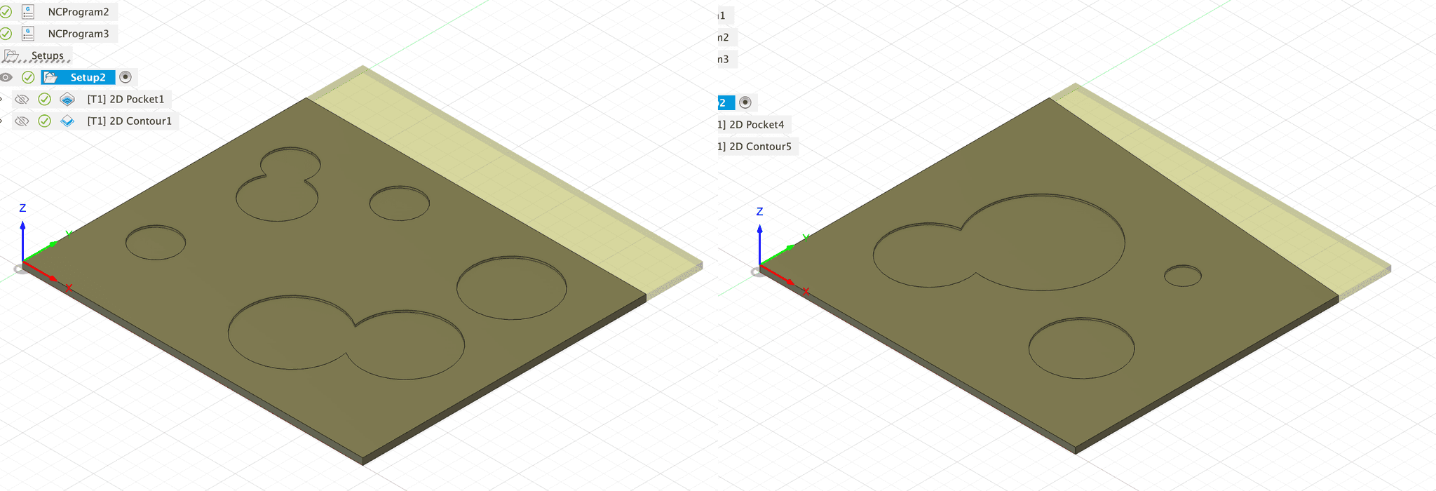
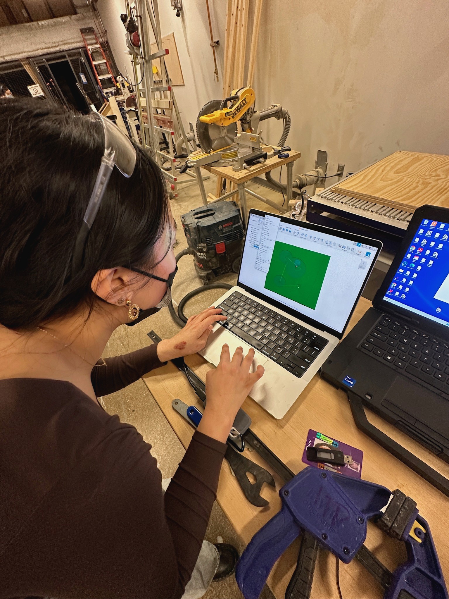
The three main exterior panels were milled using the ShopBot Desktop MAX ATC. Delaney imported the Adobe Illustrator diagram as an SVG into Fusion360 for precision and used this to model and prepare CAM files for each of the three panels. Slight adjustments had to be made to the first drafts of our files due to the cutting bed size constraints.
3D Earth Model
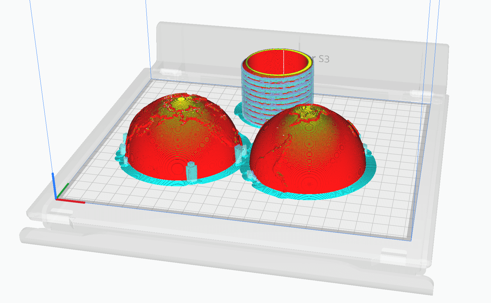
Delaney resized a screwable model of the Earth to fit the dimensions of the Arduino and BLE module and imported it into Ultimaker Cura in order to print it using PLA on the Ultimaker S3 machine.
Our print failed three times in a row, each with different infill, speed, and support type settings. This was an unexpected and frustrating roadblock.
Cody advised us to remove supports entirely and our print was a success!
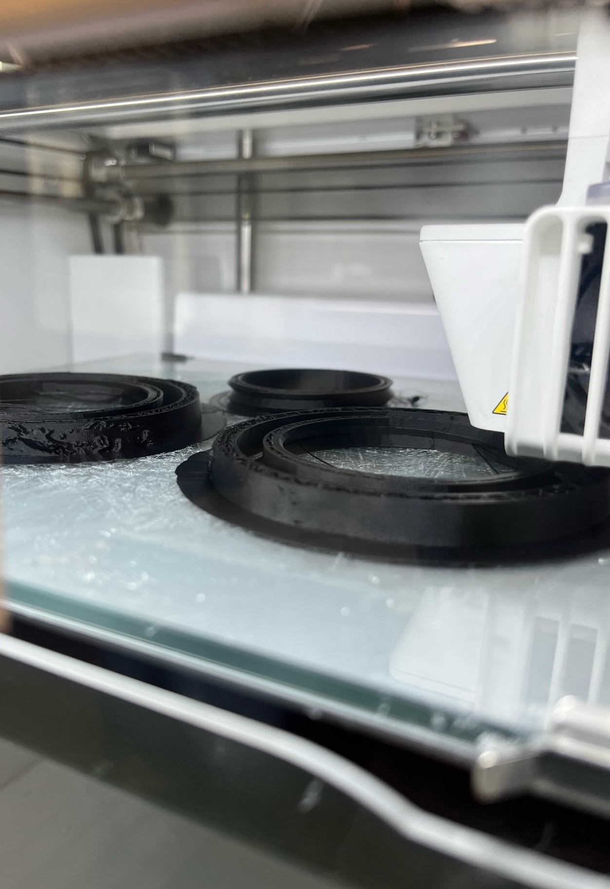
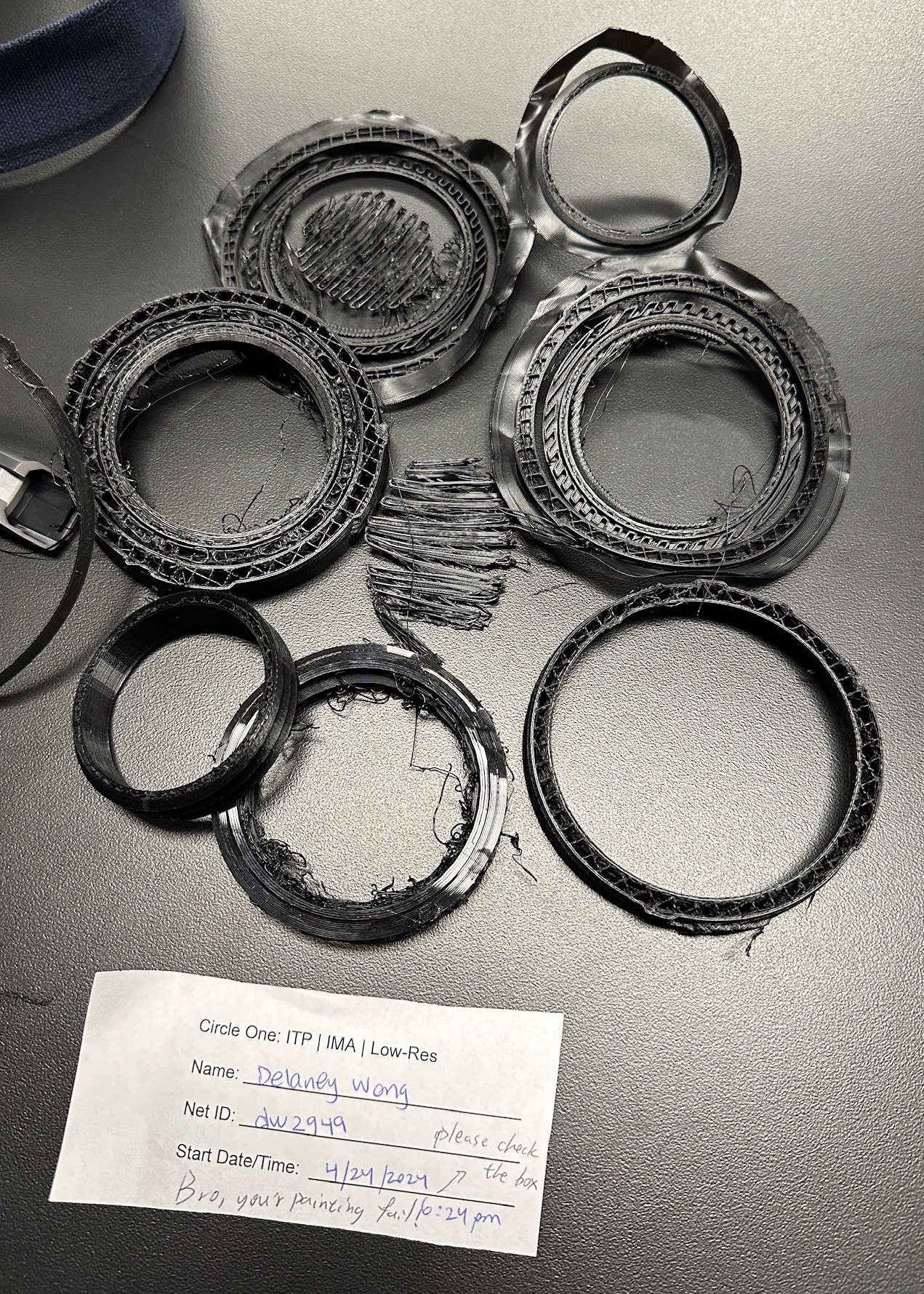
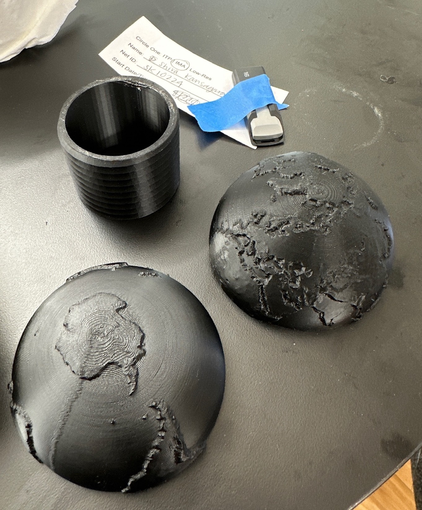
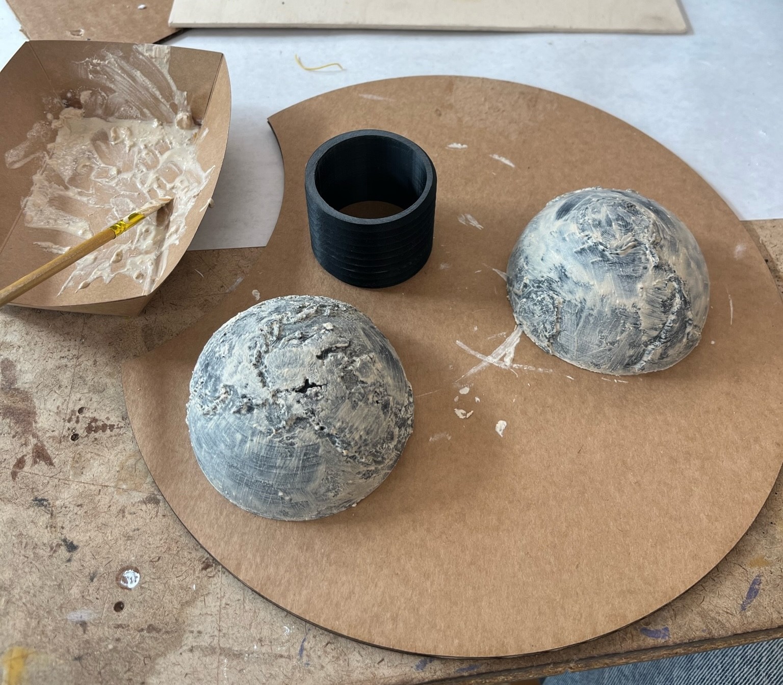
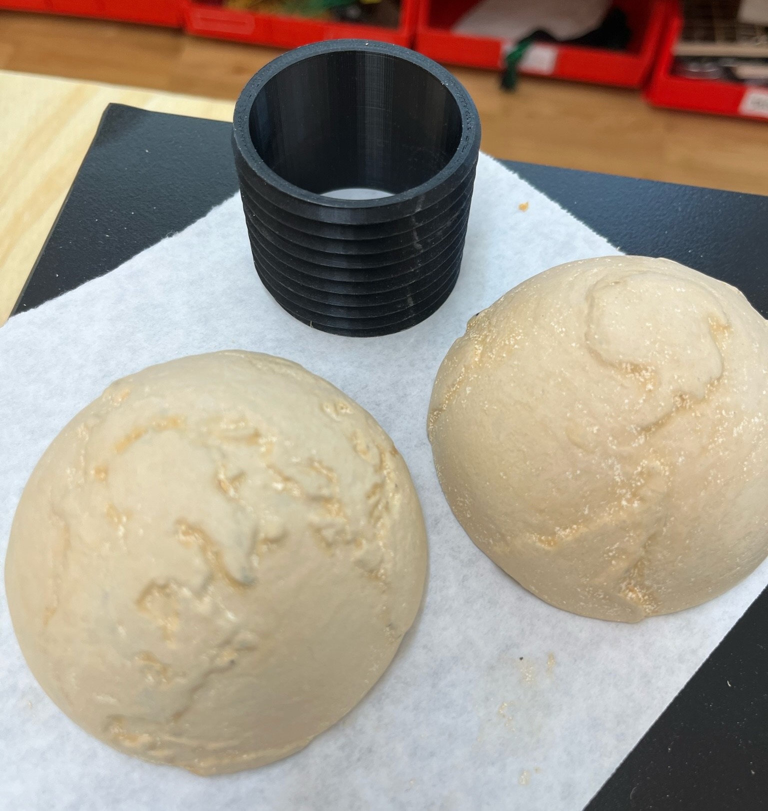
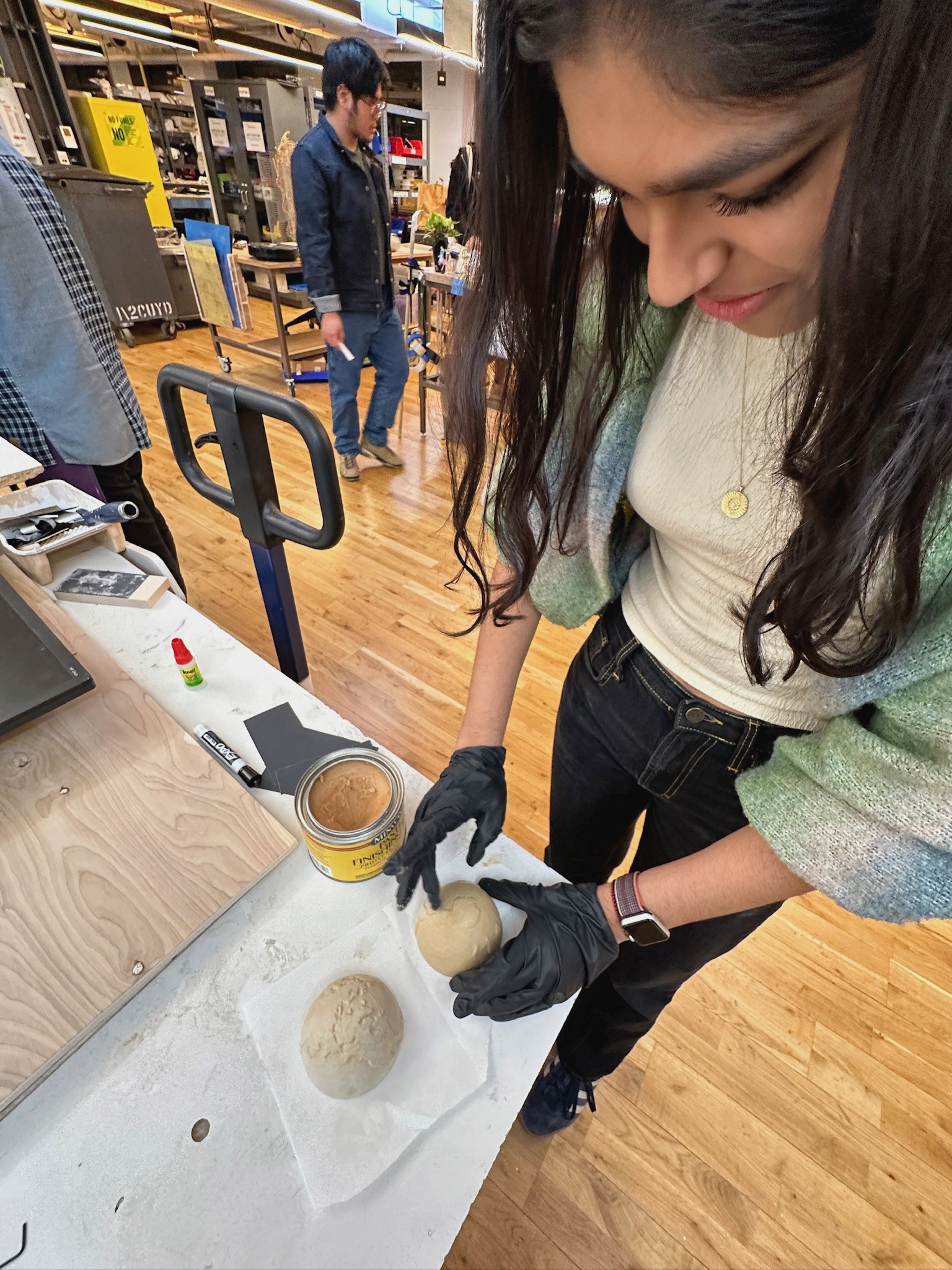
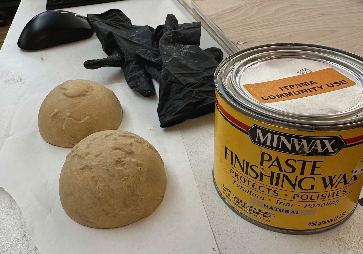
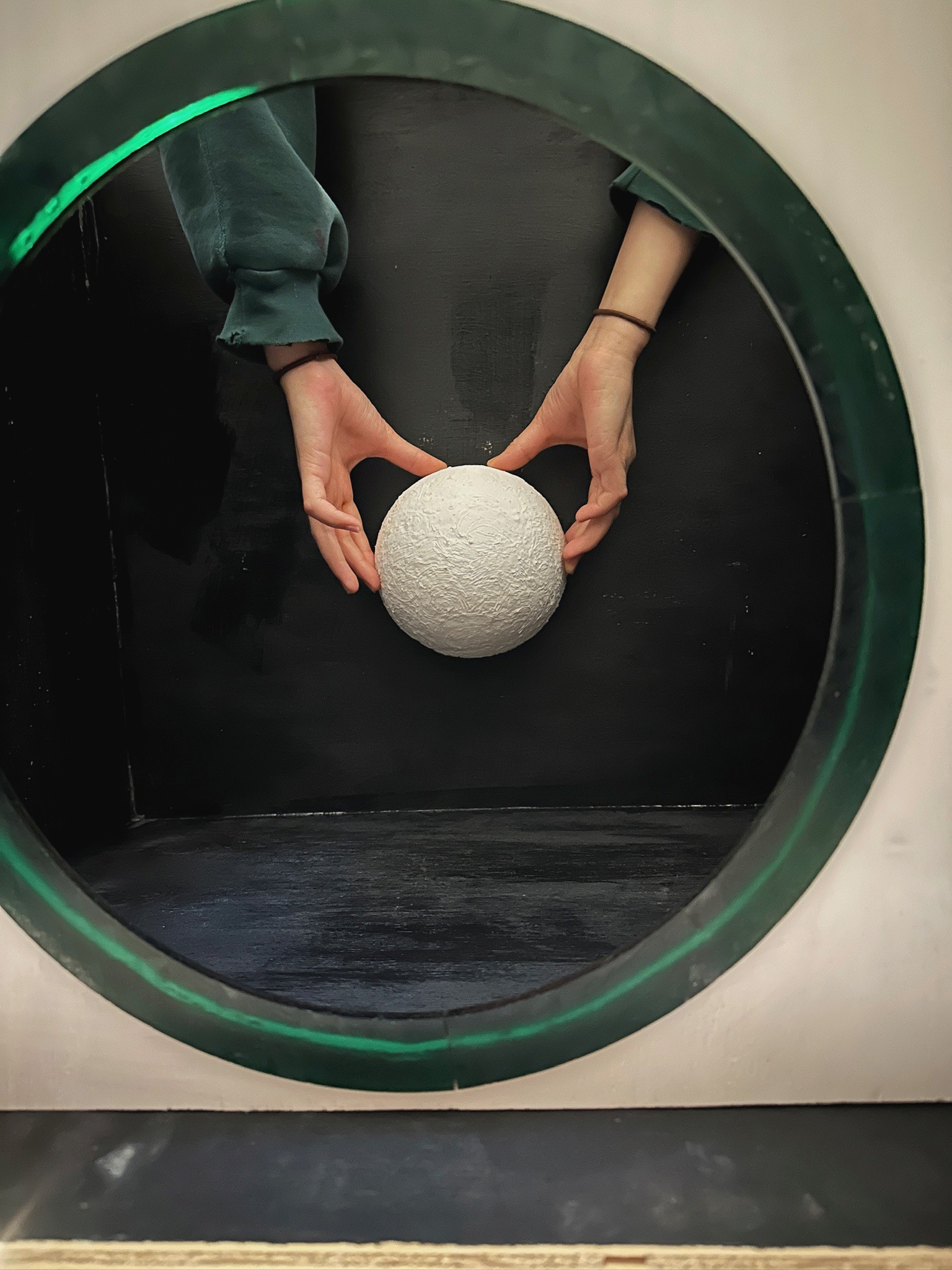
We post-processed this print by sanding and buffing, applying multiple coats of wood filler, sanding again, and then covering the controller with wax seal in order to achieve a finished and more organic texture.
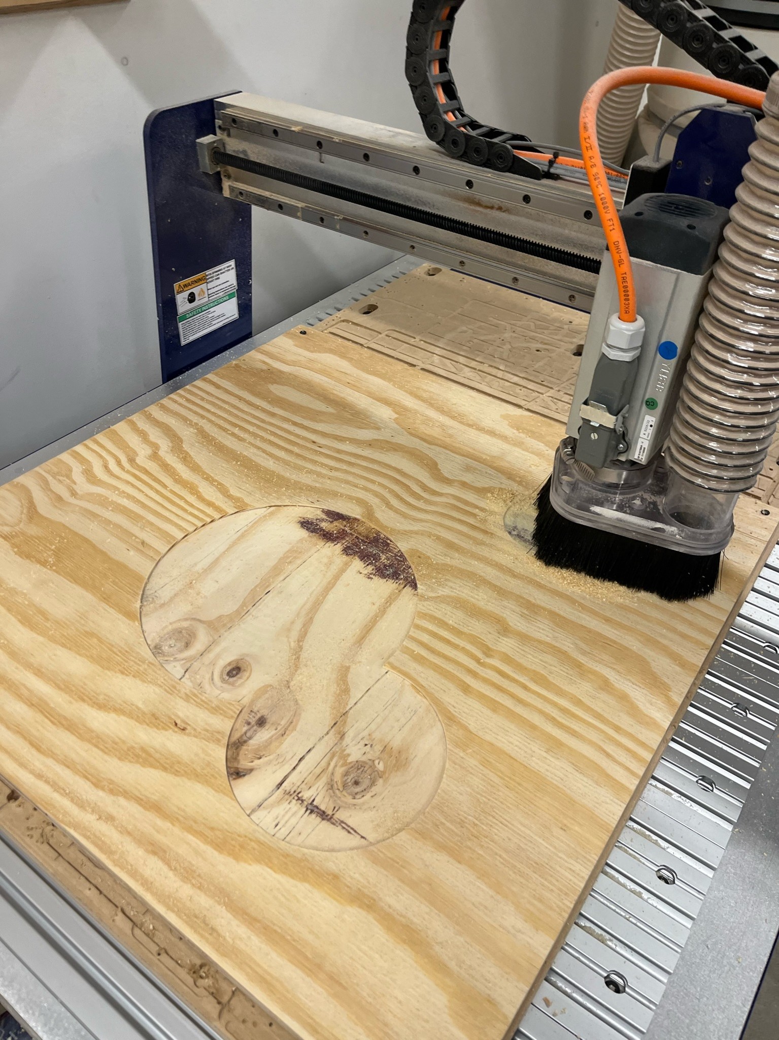
We used the ShopBot to clear out the spaces for our acrylic inserts on each of the three exterior panels and create the through cut on both of the side panels with slanted edges. Because of the amount of material that we were removing for the inserts and the simplicity of the circular shapes, we were able to use the 1/2 inch flat end bit to mill the exterior design before switching to a 1/4 inch flat end bit to mill the complete cuts with tabs and multiple depths. We ran into a few logistical challenges such as shop staff shortages, reduced operational hours, and broken machines at both the ITP basement and Tandon Makerspace, but aside from these roadblocks, the actual process of milling our pieces went smoothly and left us with very precise cuts that was extremely useful when it came to putting all of our different pieces together later down the line.
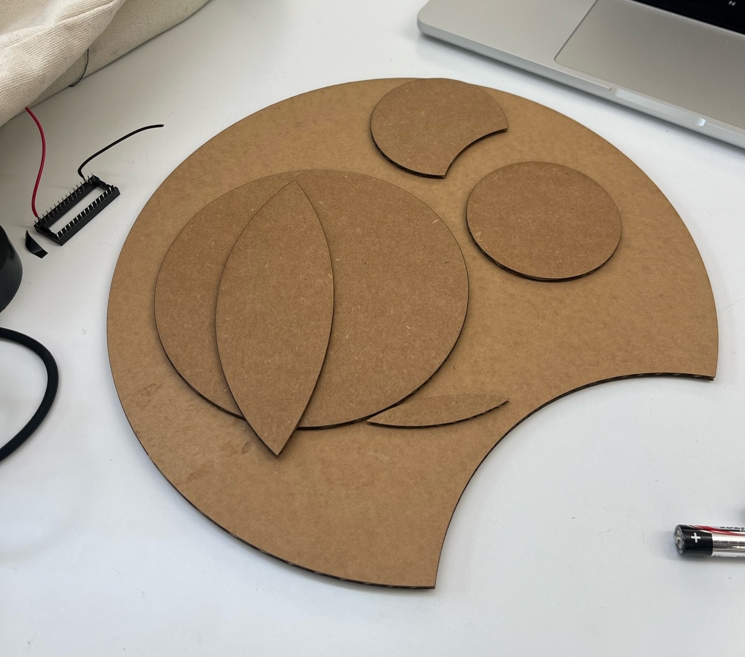
After milling our plywood and before cutting our acrylic, we laser cut cardboard inserts in order to make sure that our acrylic designs would fit snug.
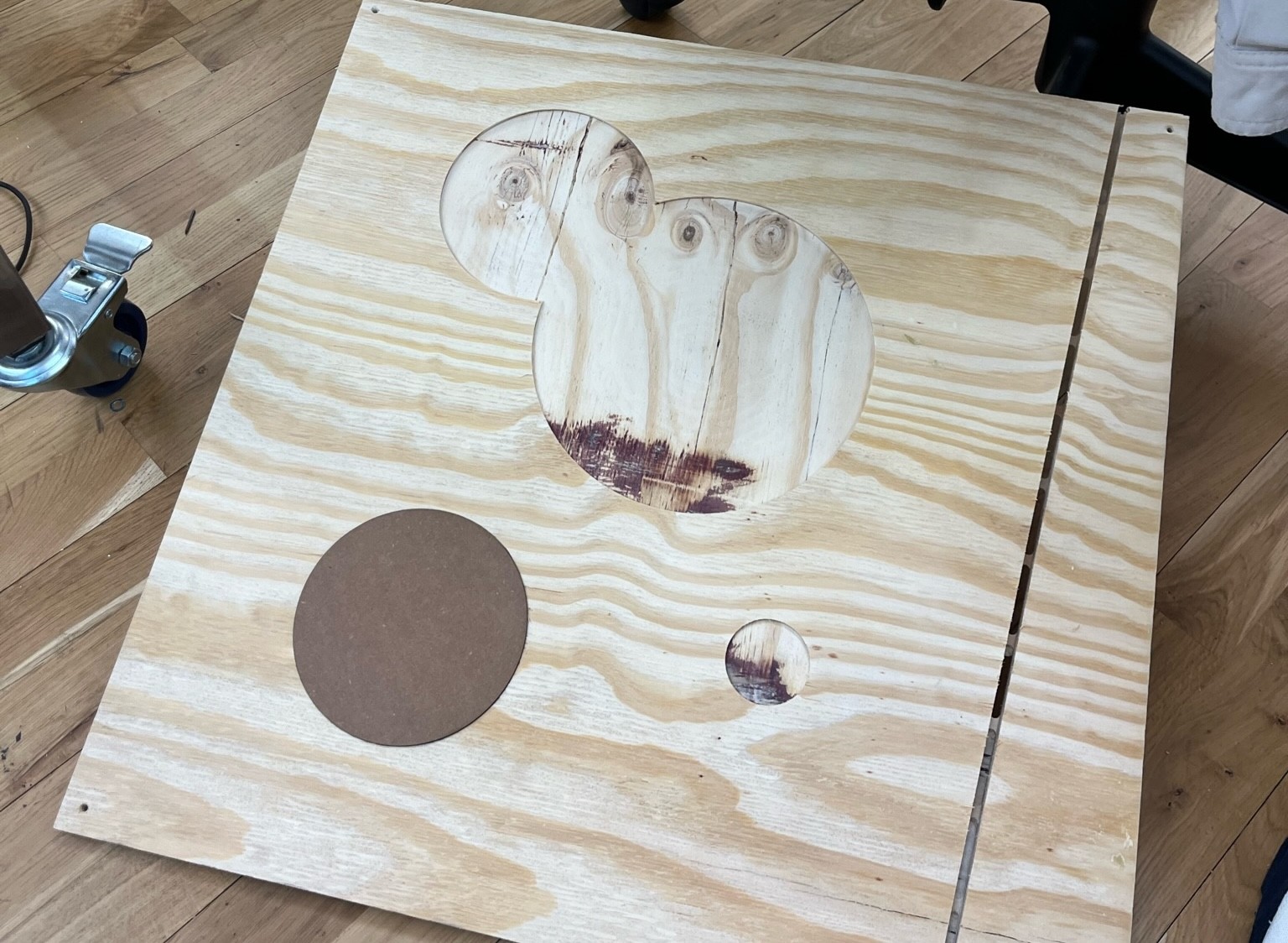
After confirming our correct dimensions, we sent our files to the Helix Mini Laser Cutter. We cut our pieces in transparent, red, transparent teal, florescent blue, and iridescent acrylic that Delaney sourced from Canal Plastics Center. These colors fit our retro design inspiration perfectly.
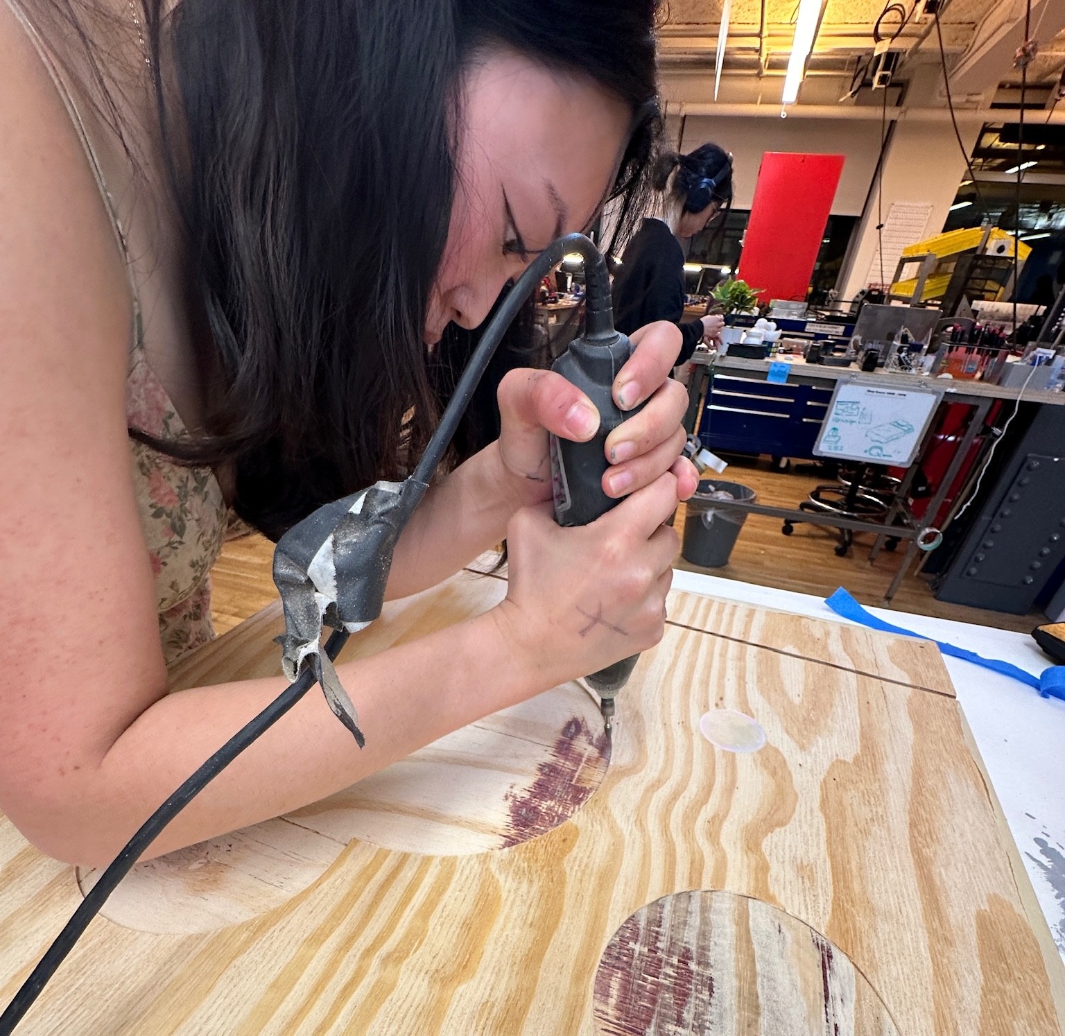
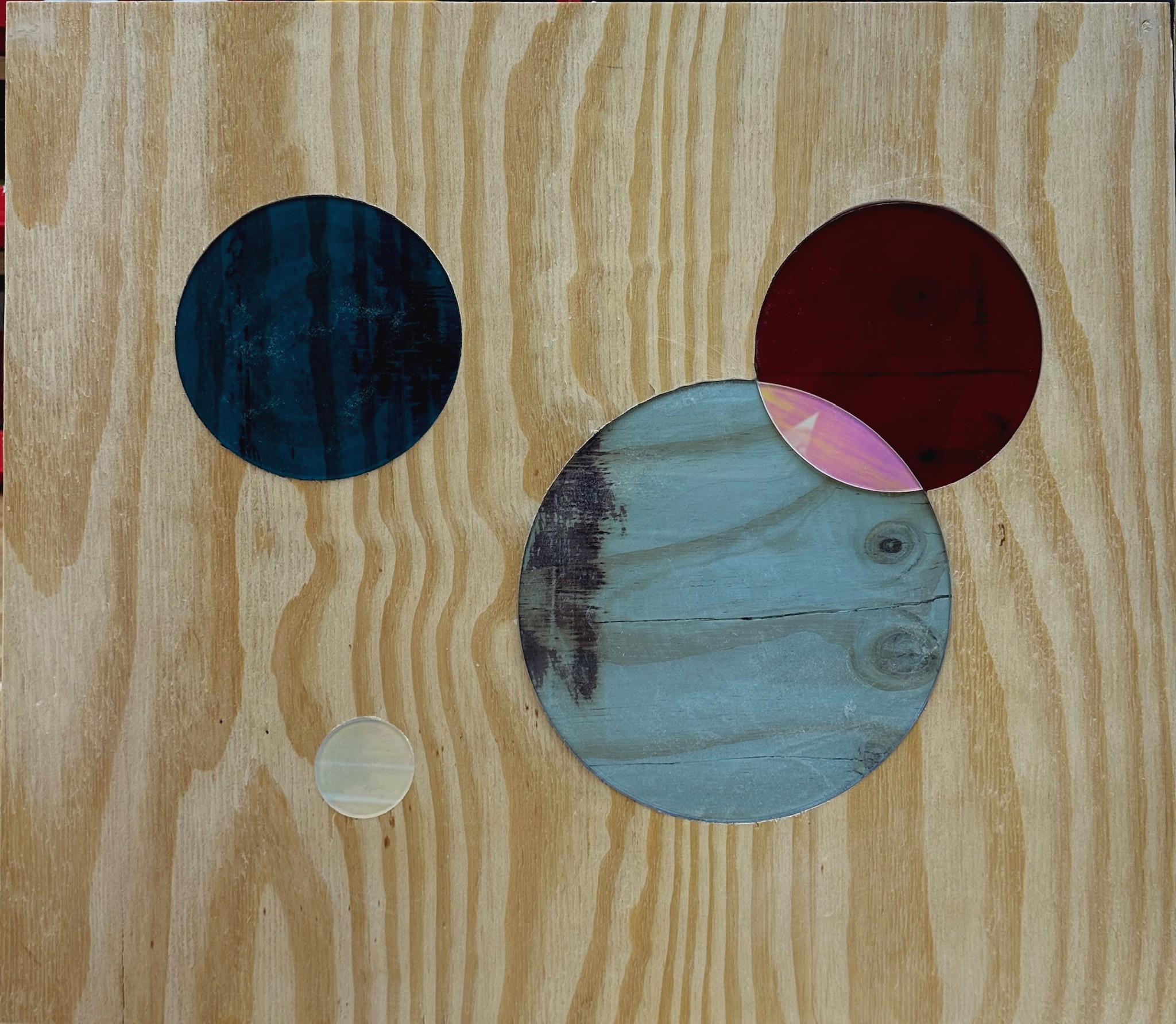
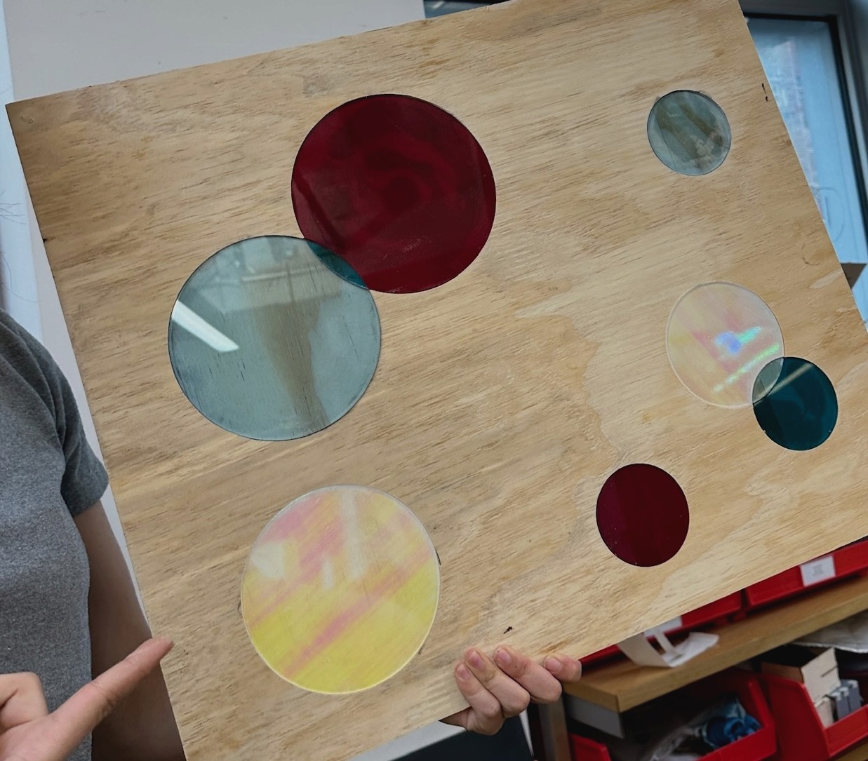
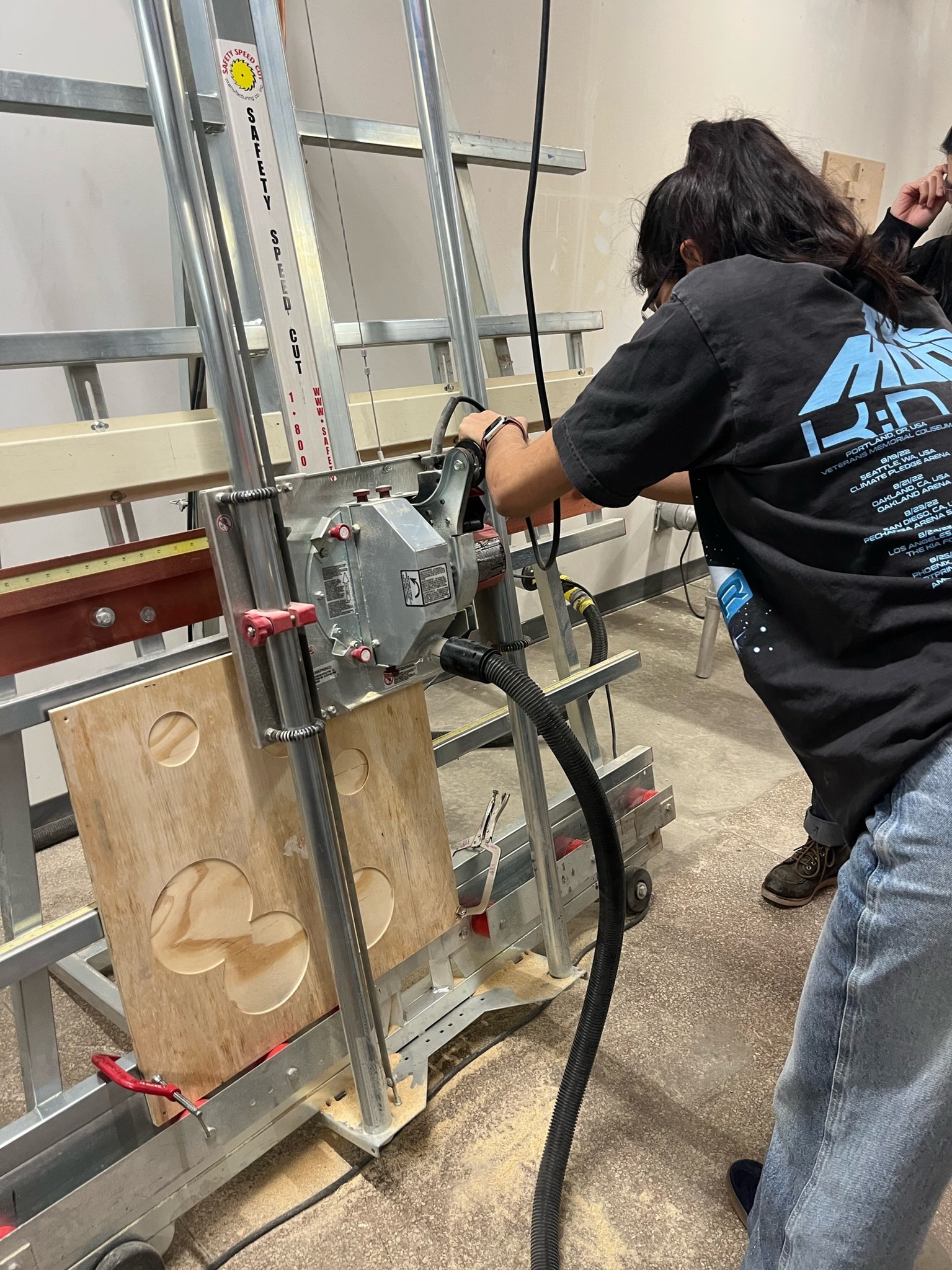
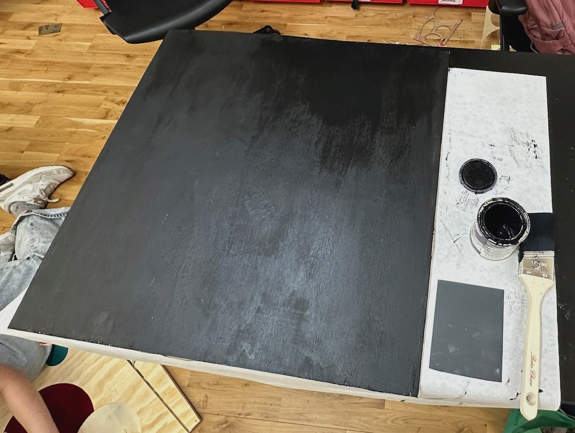
Although we tested our measurements with cardboard, some of our bigger pieces still had a hard time fitting into the milled slots; so, we sanded down the sides of some of the slots with a dremel. Next, we began adhering our acrylic to the slots on our wooden panels using weld-on. We found that between layers of plywood were darker, wavy patterns as well as weld-on residue that was visible underneath the transparent acrylic. This ended up being a happy accident because the combination of patterns revealed a planetary vibe. The middle panel was originally cut with four 90 degree angles, so we decided to remove the bottom four inches using a panel saw in order to create additional room for our user's head. After milling and cutting each of these panels, we coated all of the sides that would form the interior of the structure with black paint.
Next, we began assembling our wooden panels. Originally, we thought we would have to drill or nail together the panels, but after consulting the Shop Staff, we learned that using wood glue and right-angle clamps would be the best way to ensure a sturdy structure and a polished look from the inside. This part of construction ended up being a lot trickier than we imagined due to the slight difference in the height of our panels and a few less-than-90-degree angles that made up our structure –– effectively clamping the panels together took some trial and error. Shoutout to our friend Mickey for supporting us in this delicate process.
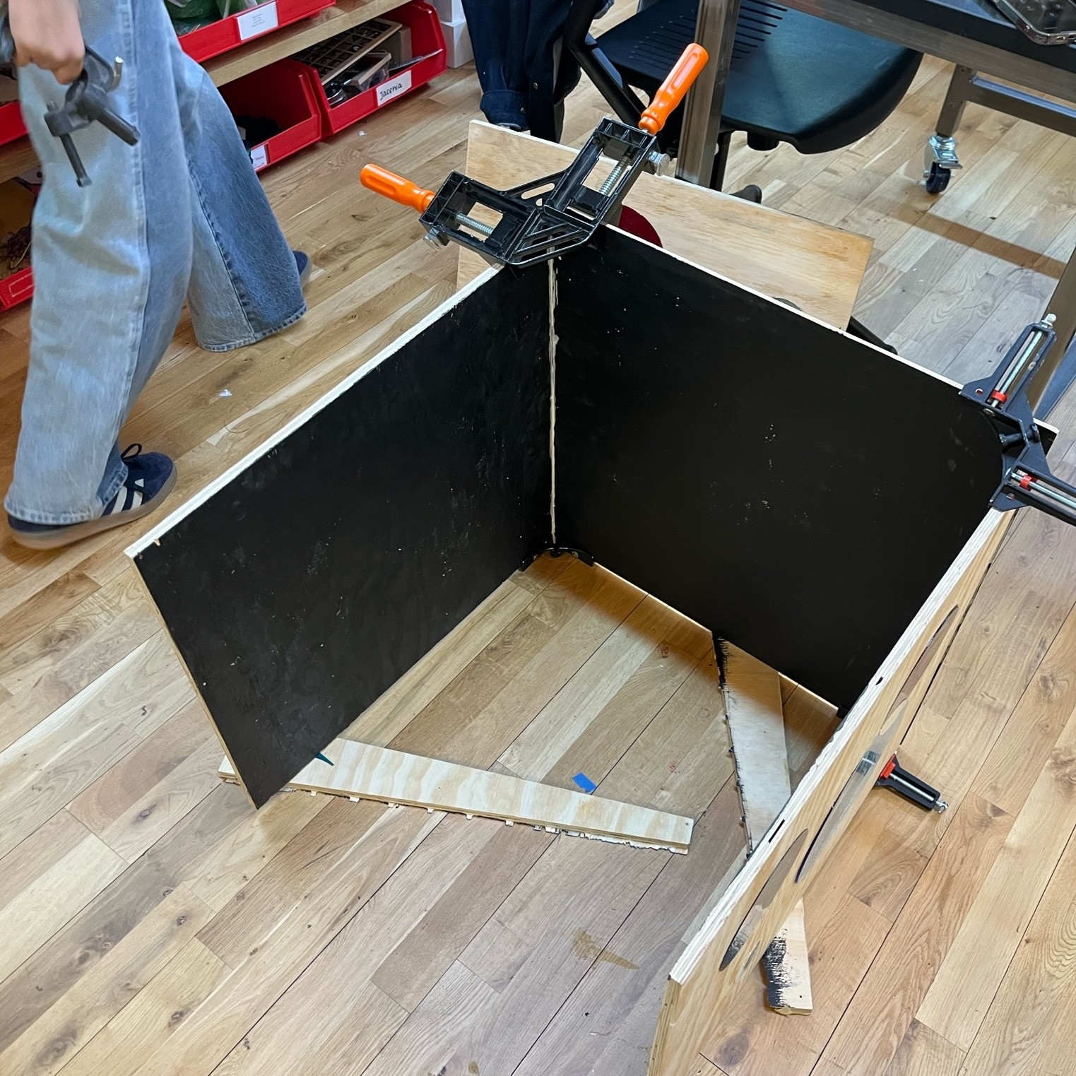
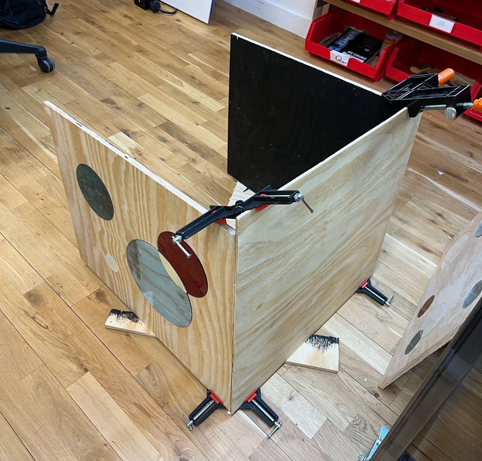
Luckily, we came back in the morning to find that our attempt was successful! After cleaning up some of the glue that had leaked through the cracks, we were left with a polished enclosure.
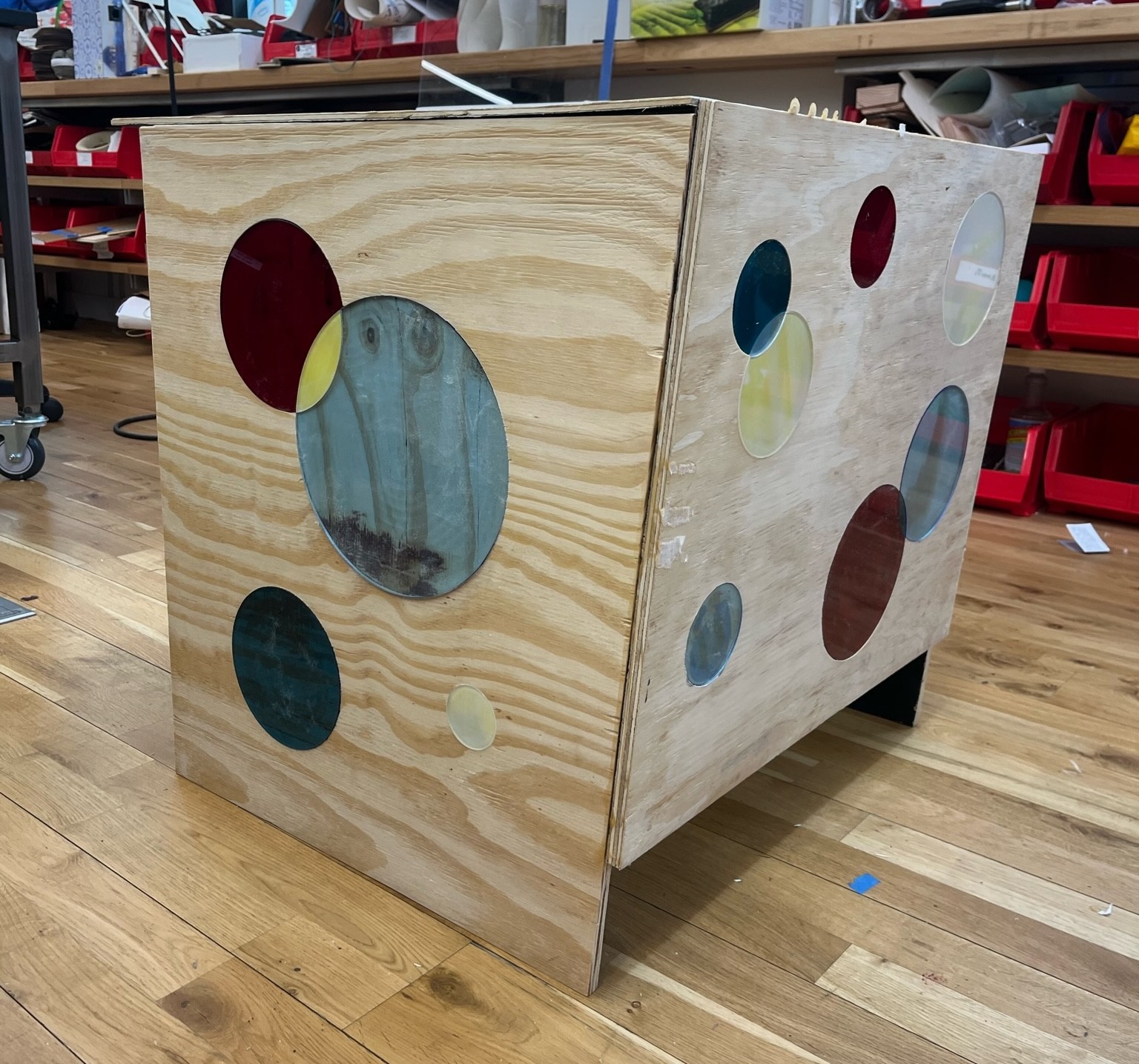
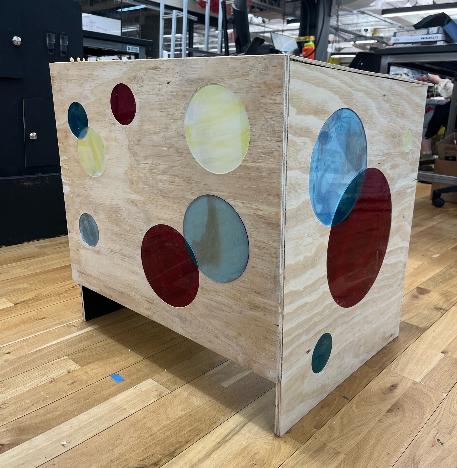
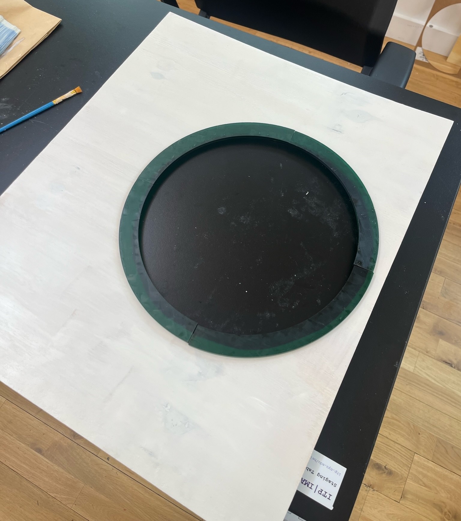
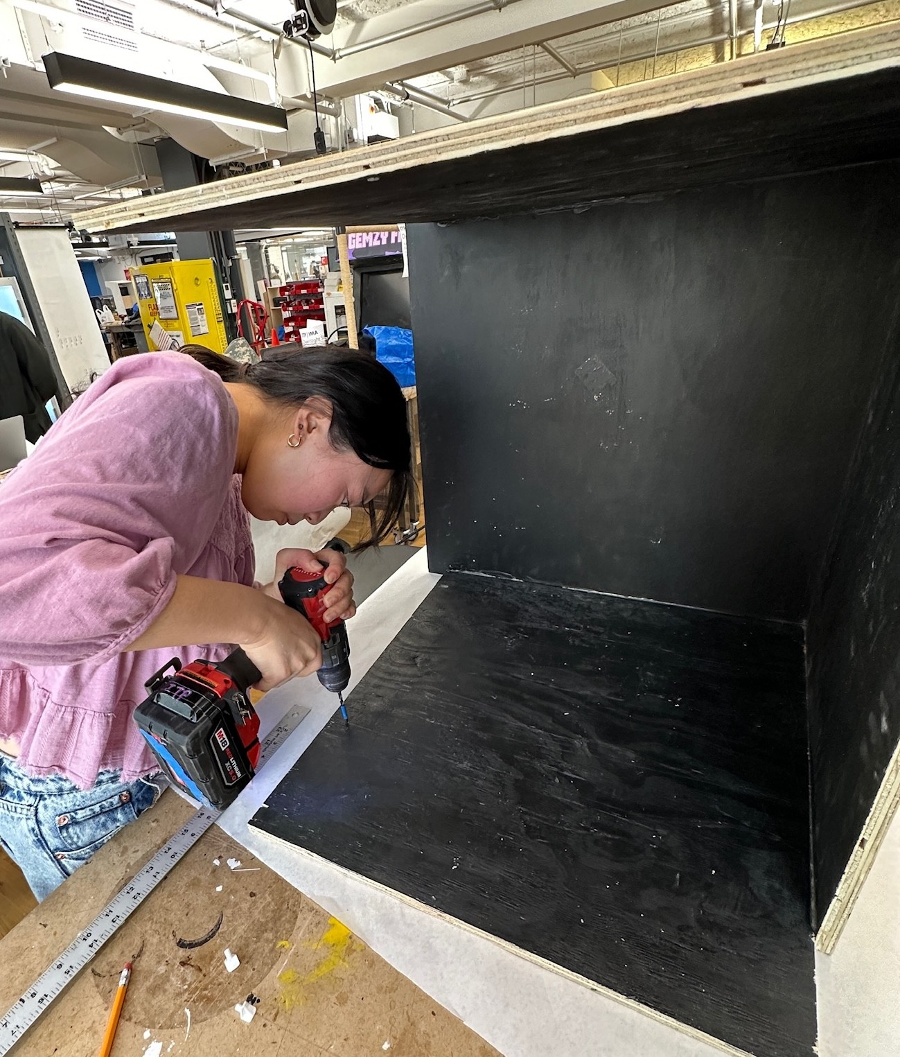
The next step was to construct, paint, and install the shelf that would rest inside the enclosure and serve as both the window between the user and the model as well as the platform for the projector to rest on. We constructed this out of a thinner (1/4 inch) piece of plywood. We drilled a hole into it using many smaller drill bits, then rounded it out using a dremel and by hand sanding. Looking back, there could have been a more efficient way to do this, but logistical constraints of using the CNC prevented that route.
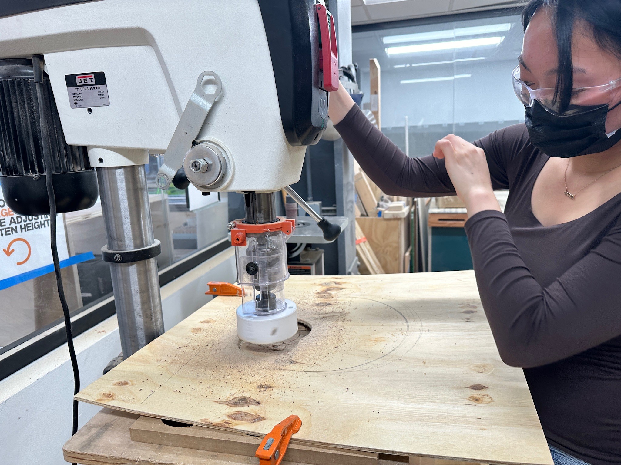
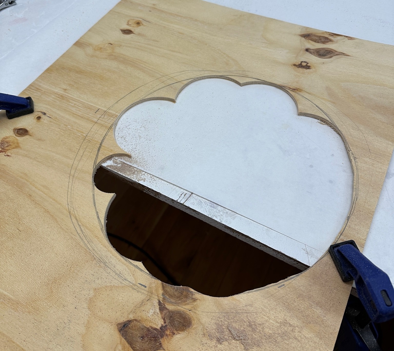
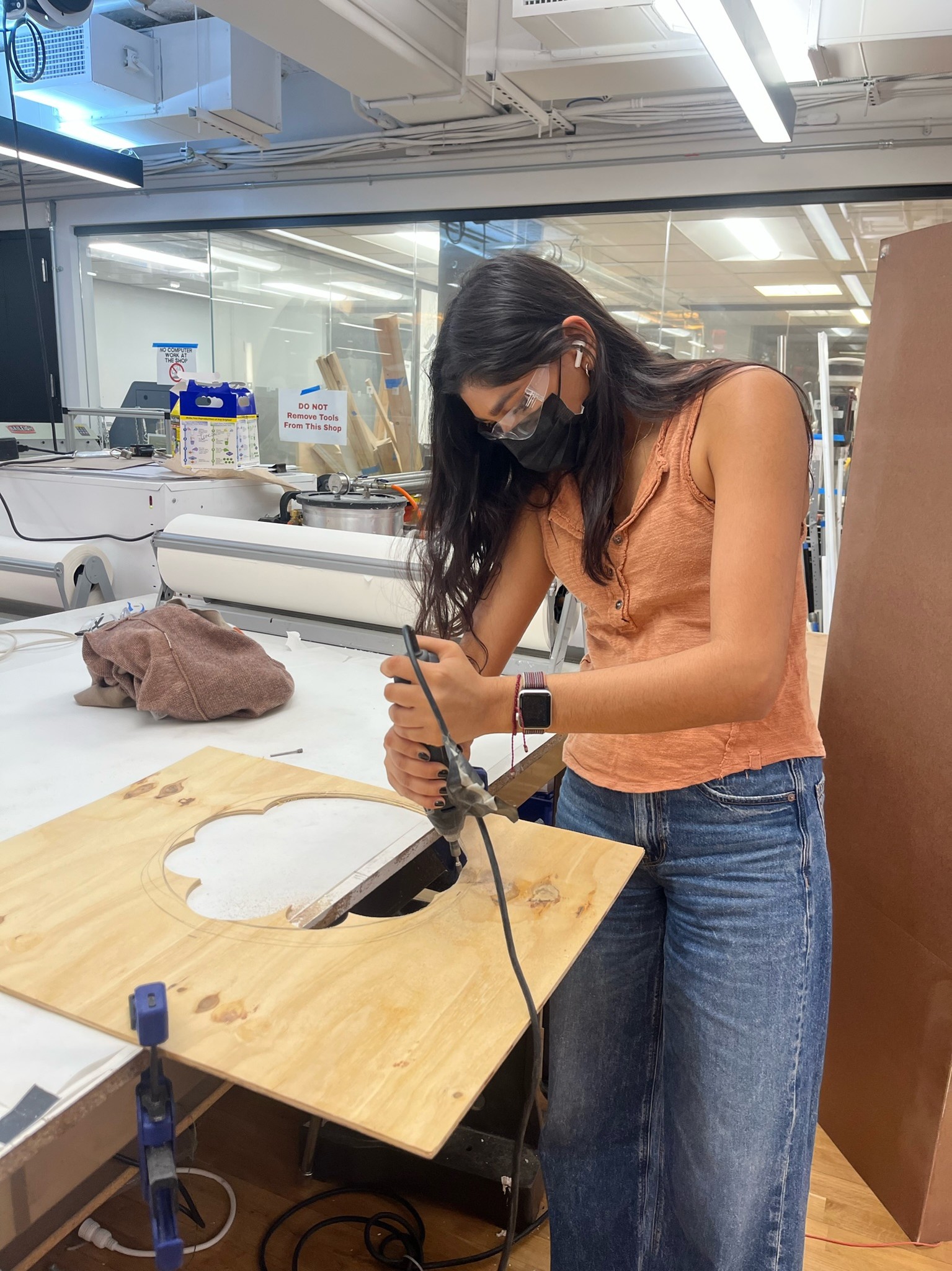
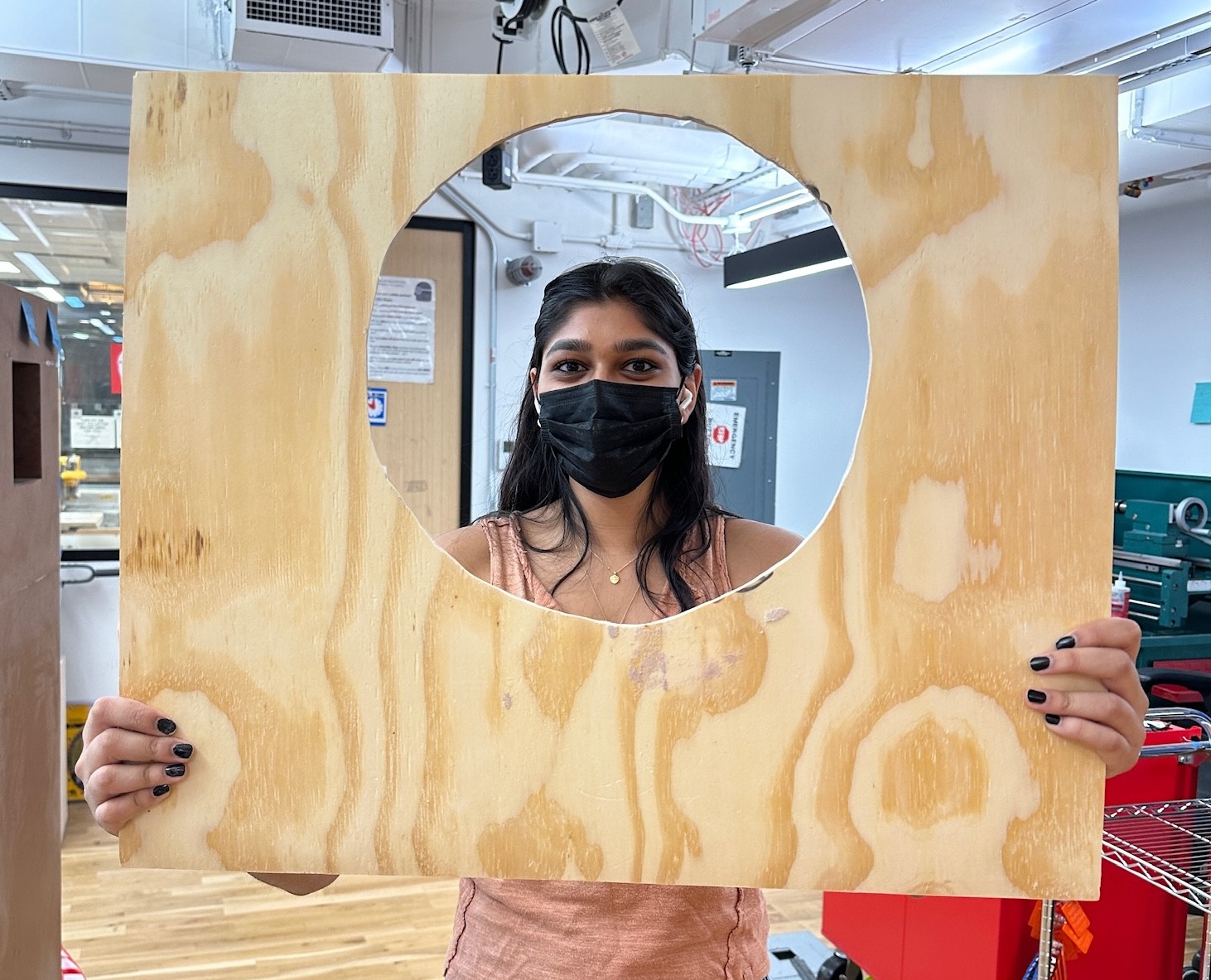
We painted the panel white to add dimension to the spacecraft. We found some dark green scrap acrylic and used the Epilog Pro Laser Cutter to cut out the circle outline. We attached the window detail using weld-on. To install this panel, we measured out our desired height and then installed shelf supports into the sides of the enclosure just under where we wanted the shelf to lay inside our exhibit.

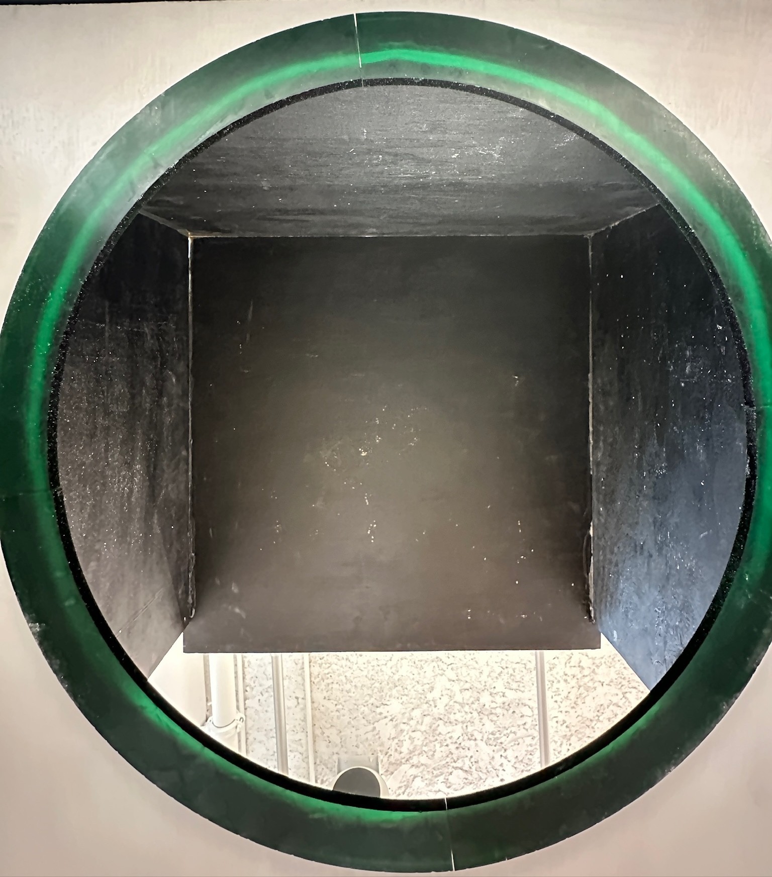

We prepped the dome for projection mapping using modeling paste and installed it onto the roof of the enclosure.
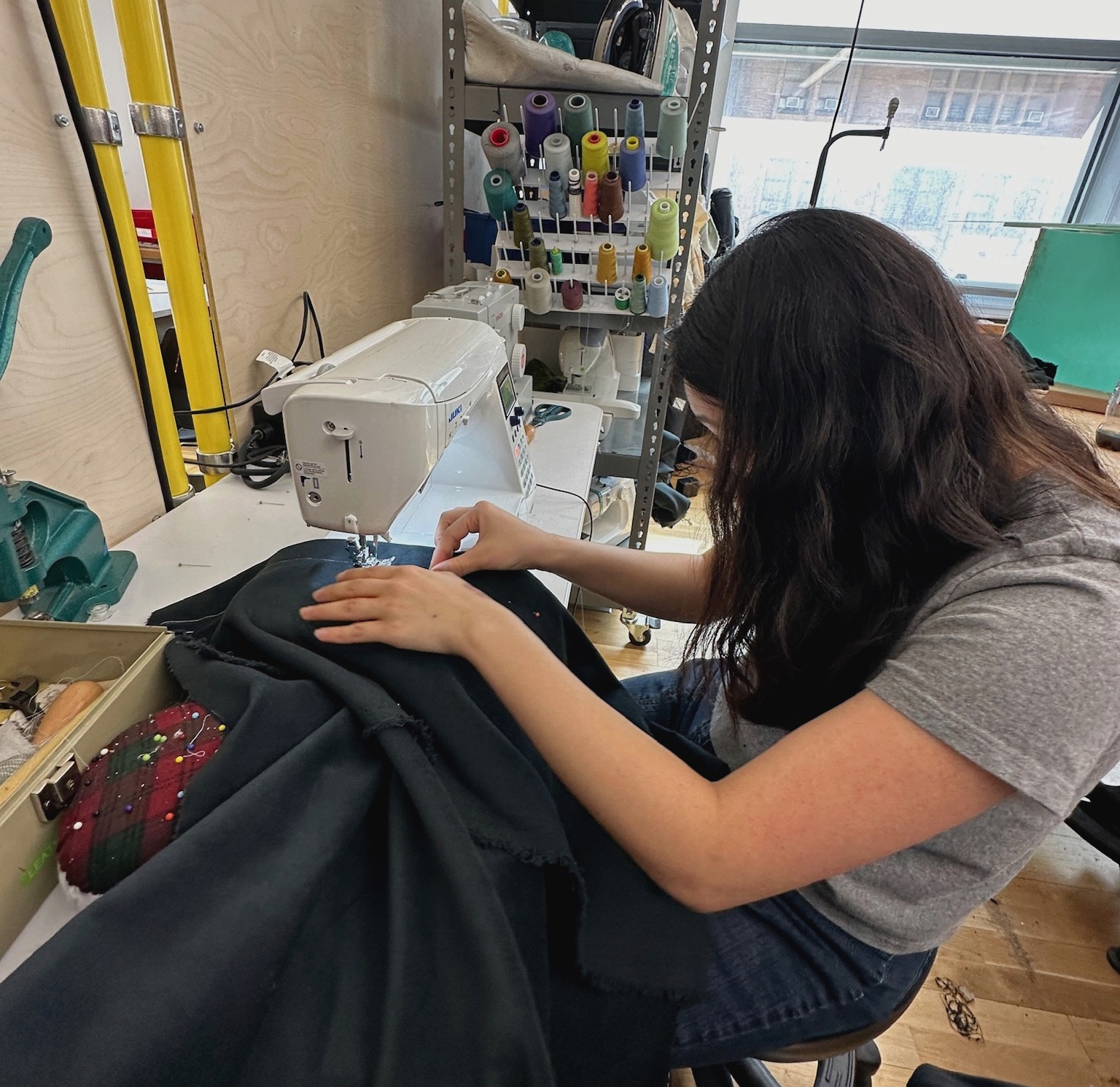
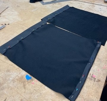
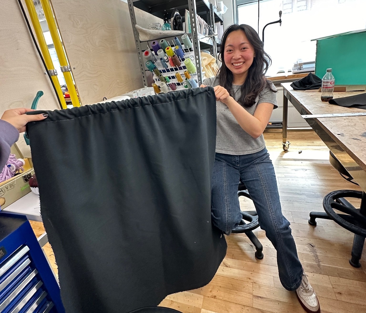
In order to improve the experience for our users inside the enclose, we decided to make and install black curtains in the front and back panels. The rear curtains would hide the projector and controller mechanisms. We sewed scrap fabric using the sewing machine to create the curtains. We used a tension role, as well as a gardening pole that was attached with command hooks, to secure the curtains in place.
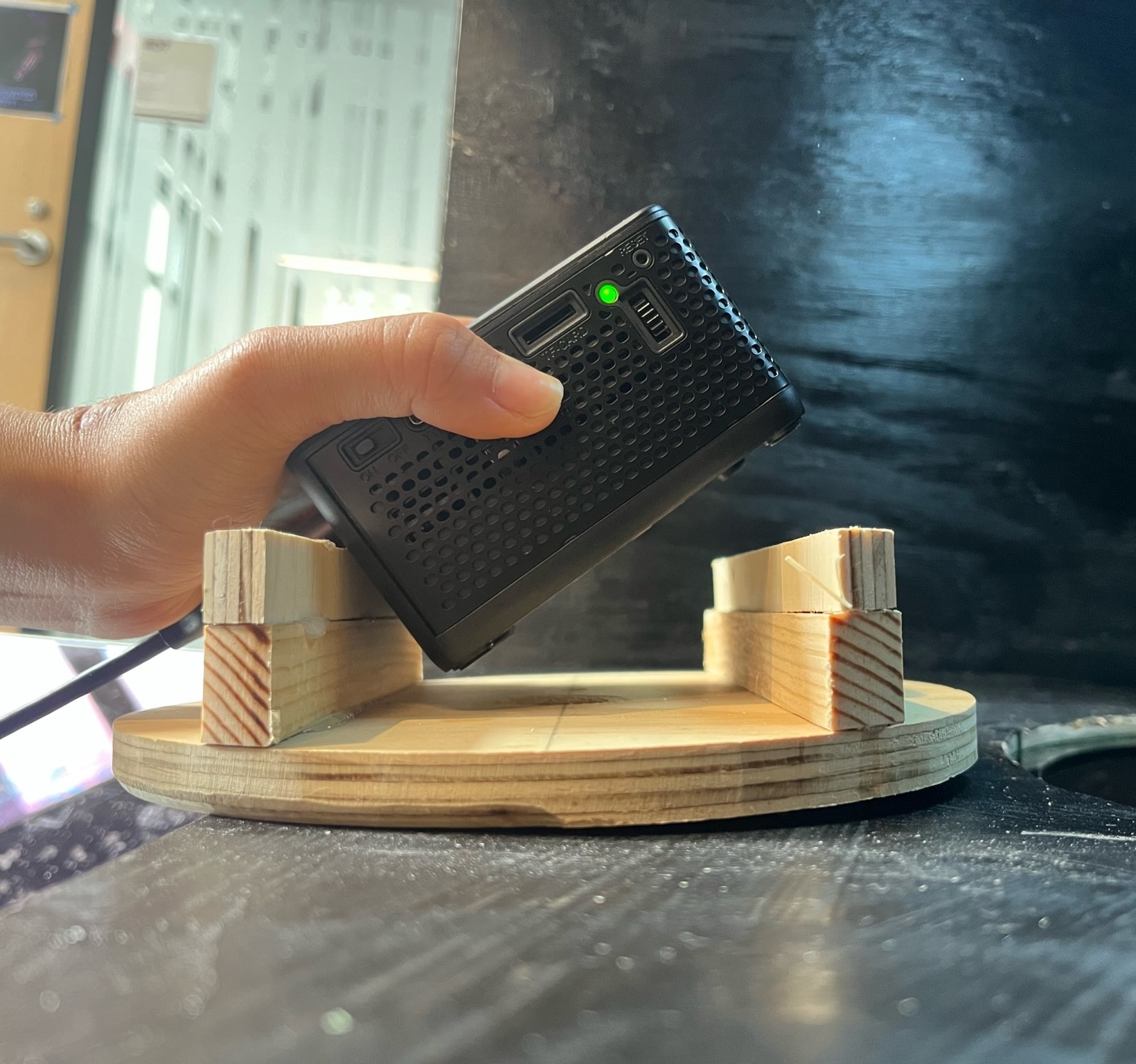
In order to projection map the Three.js model onto the dome-shaped foam piece, we used an AAXA P7+ projector –– small, but powerful. We repurposed a wooden stand from an earlier project to help hold the projector in place.
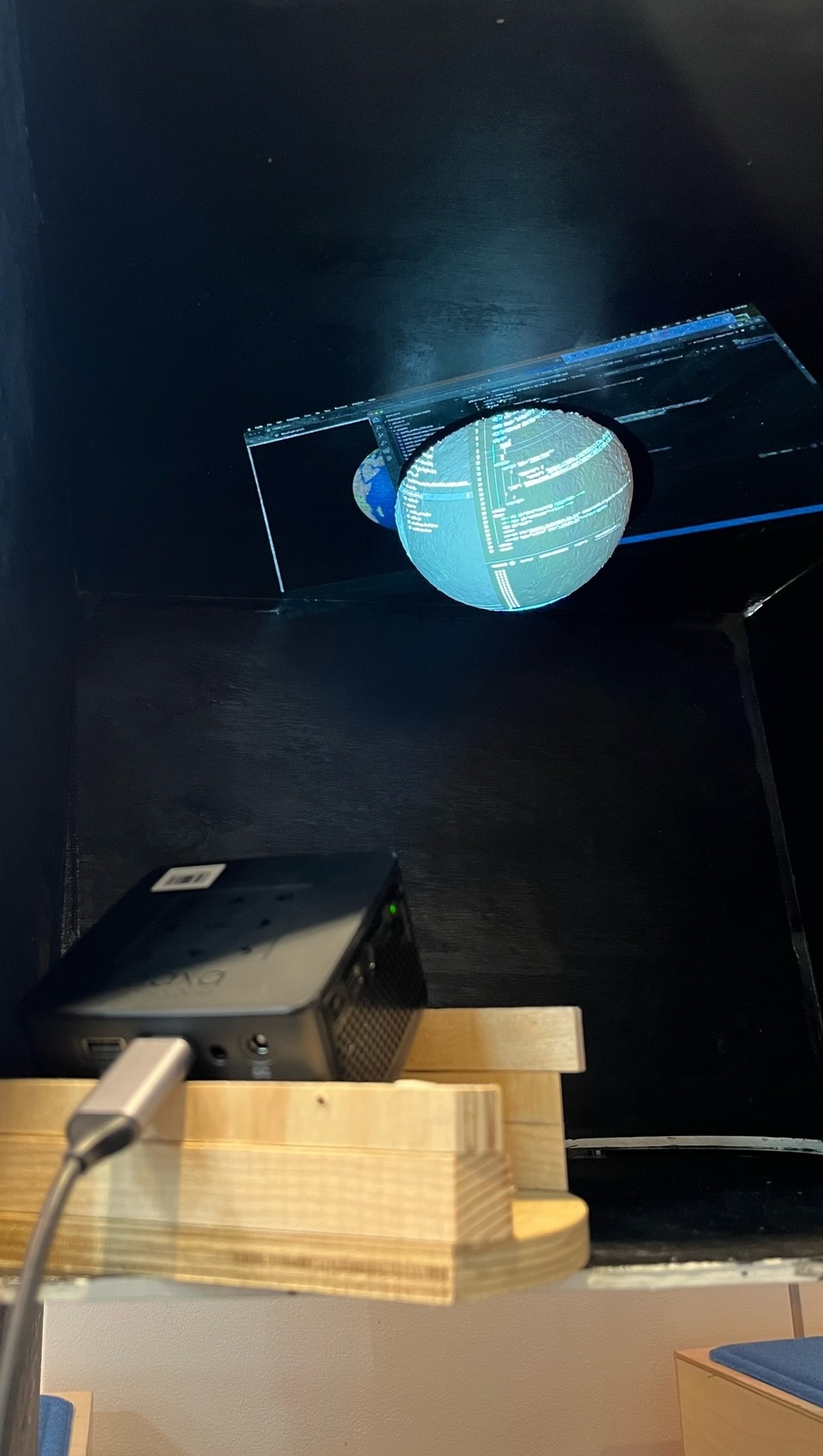
Our code, projection, and fabrication were in a finished enough state, so we user tested on our classmates and professor. We received positive feedback; they commented on our polished fabrication and working code. Many passersby seemed intrigued by the unique interaction format: physically getting down on the floor to look up at a “something” that is not revealed until actually poking your head inside.
Design postcards (in Figma) with thought-provoking discussion questions related to The Overview Effect and Vibrant Matter to build community.
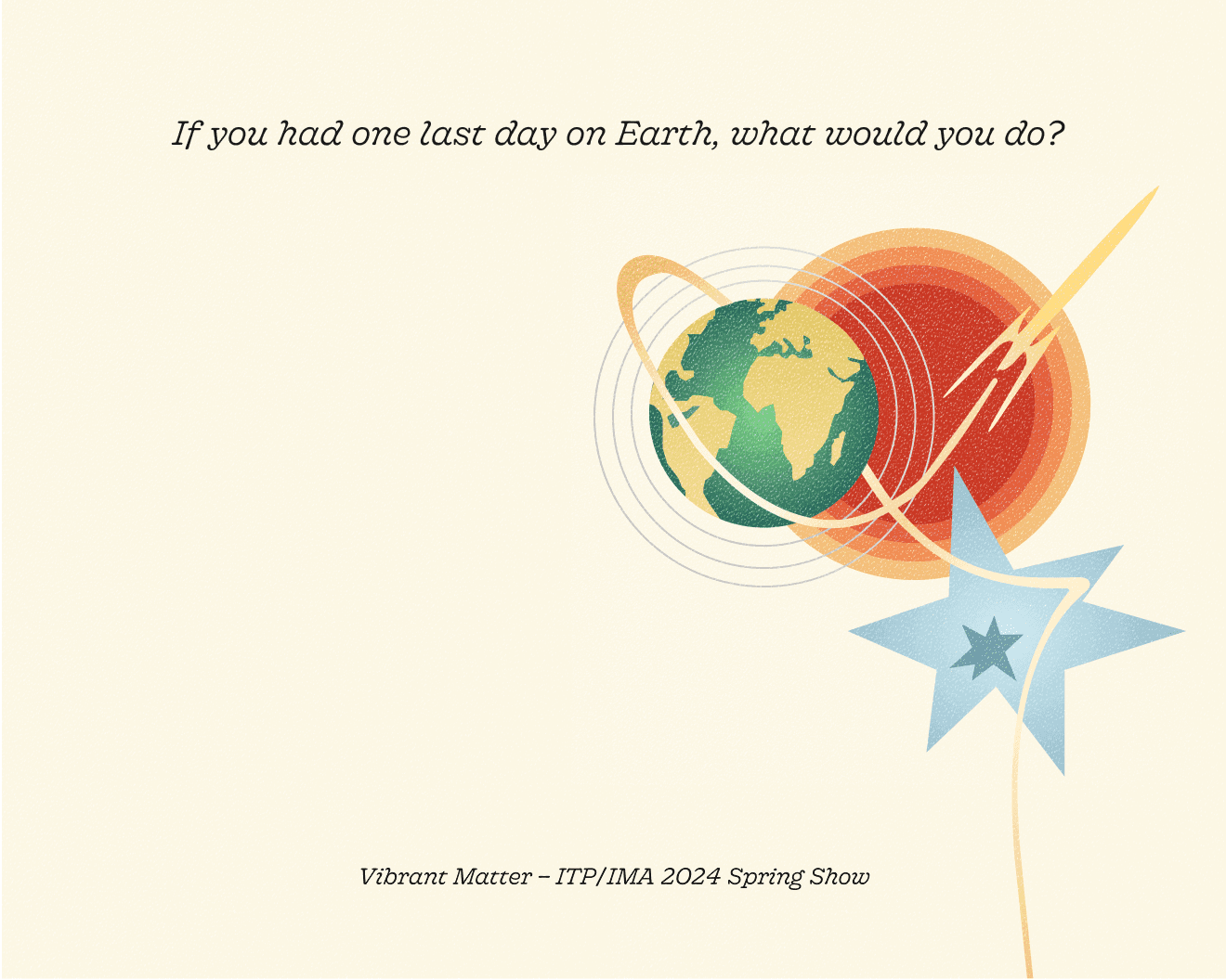
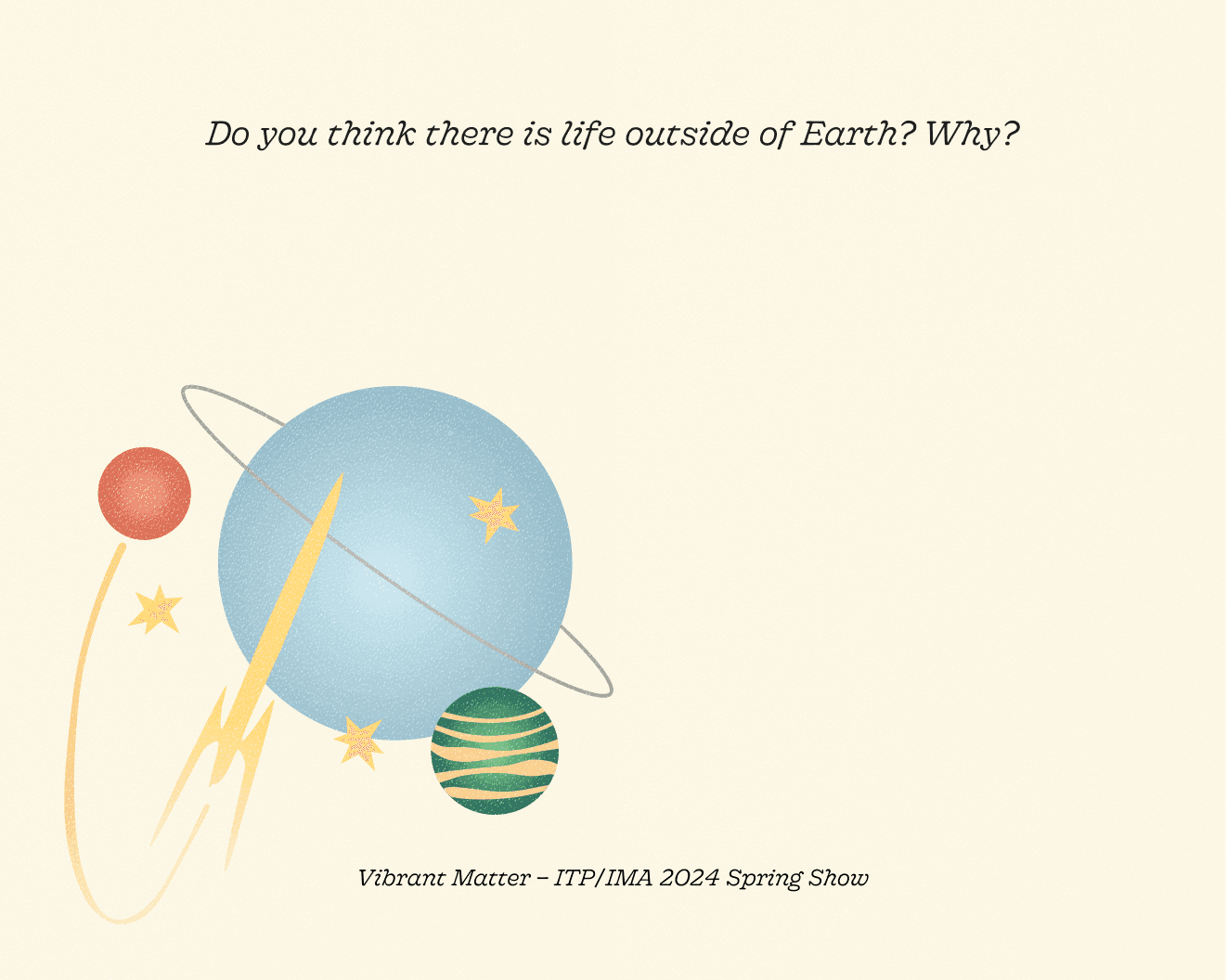
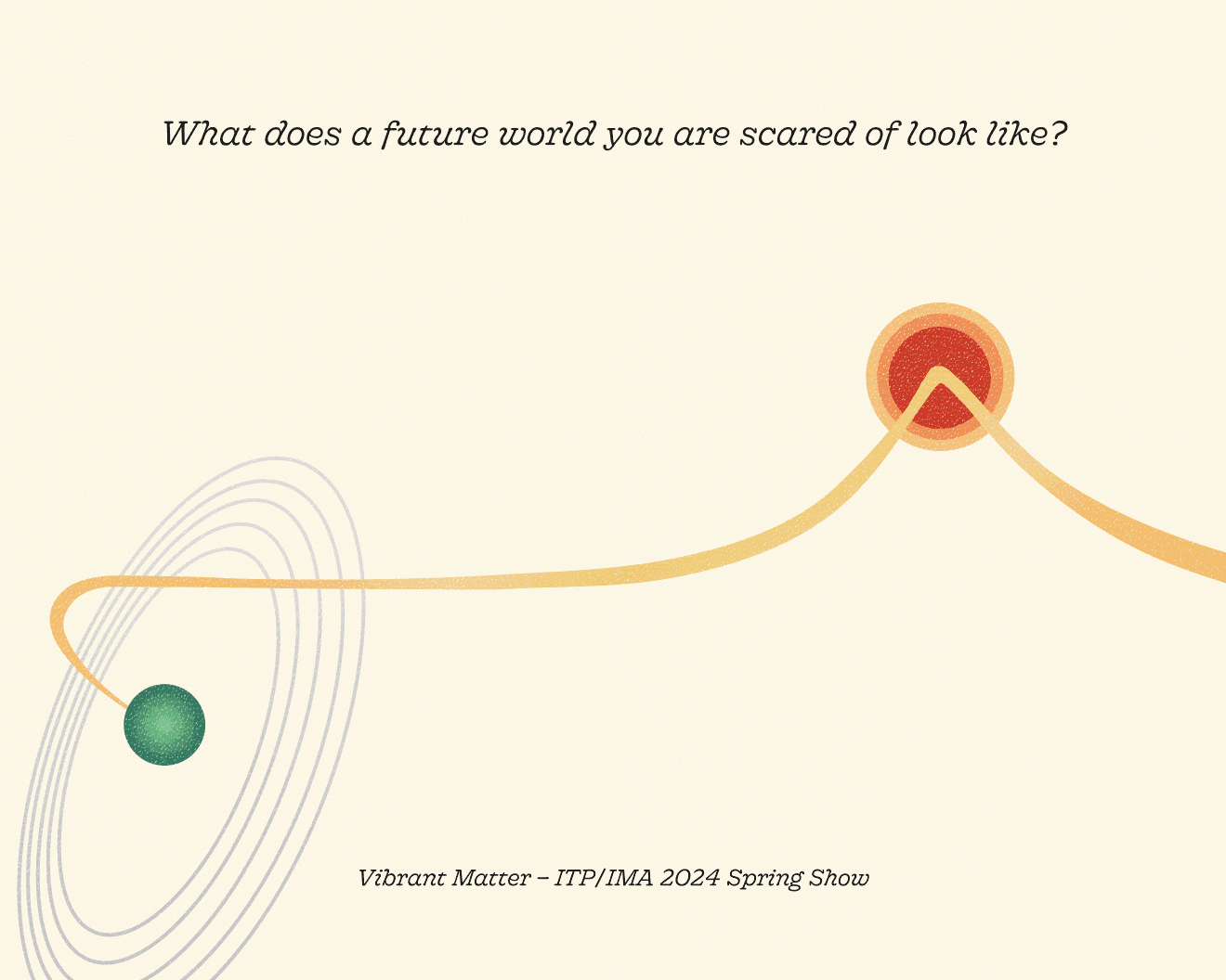
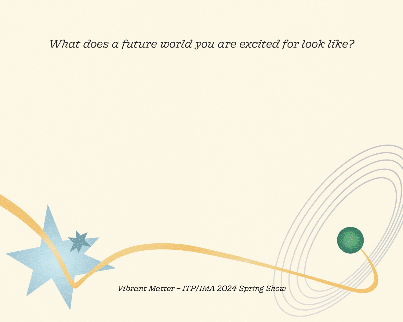
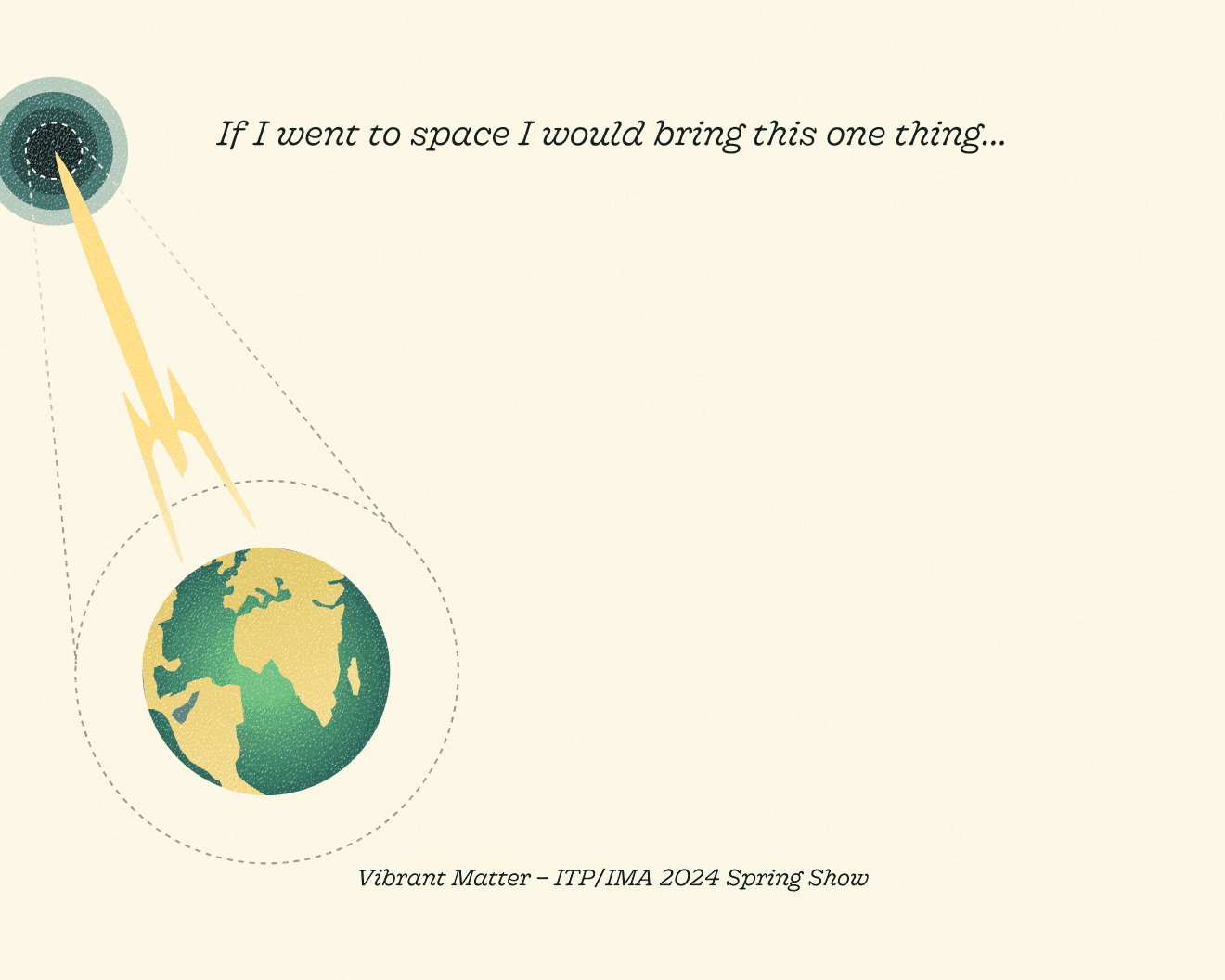
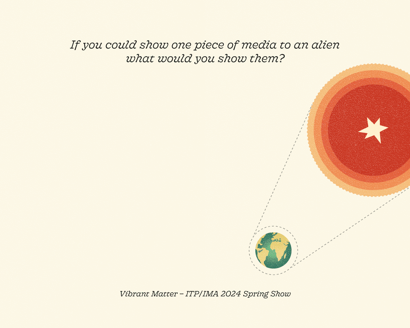
FINISHED PROJECT
Simulate the feeling of looking at Earth from space with its associated emotions and shifts in perspective
Design within the constraints of our spacial, temporal, and technical limitations
Incorporate a user-controlled interaction and opportunity for playfulness
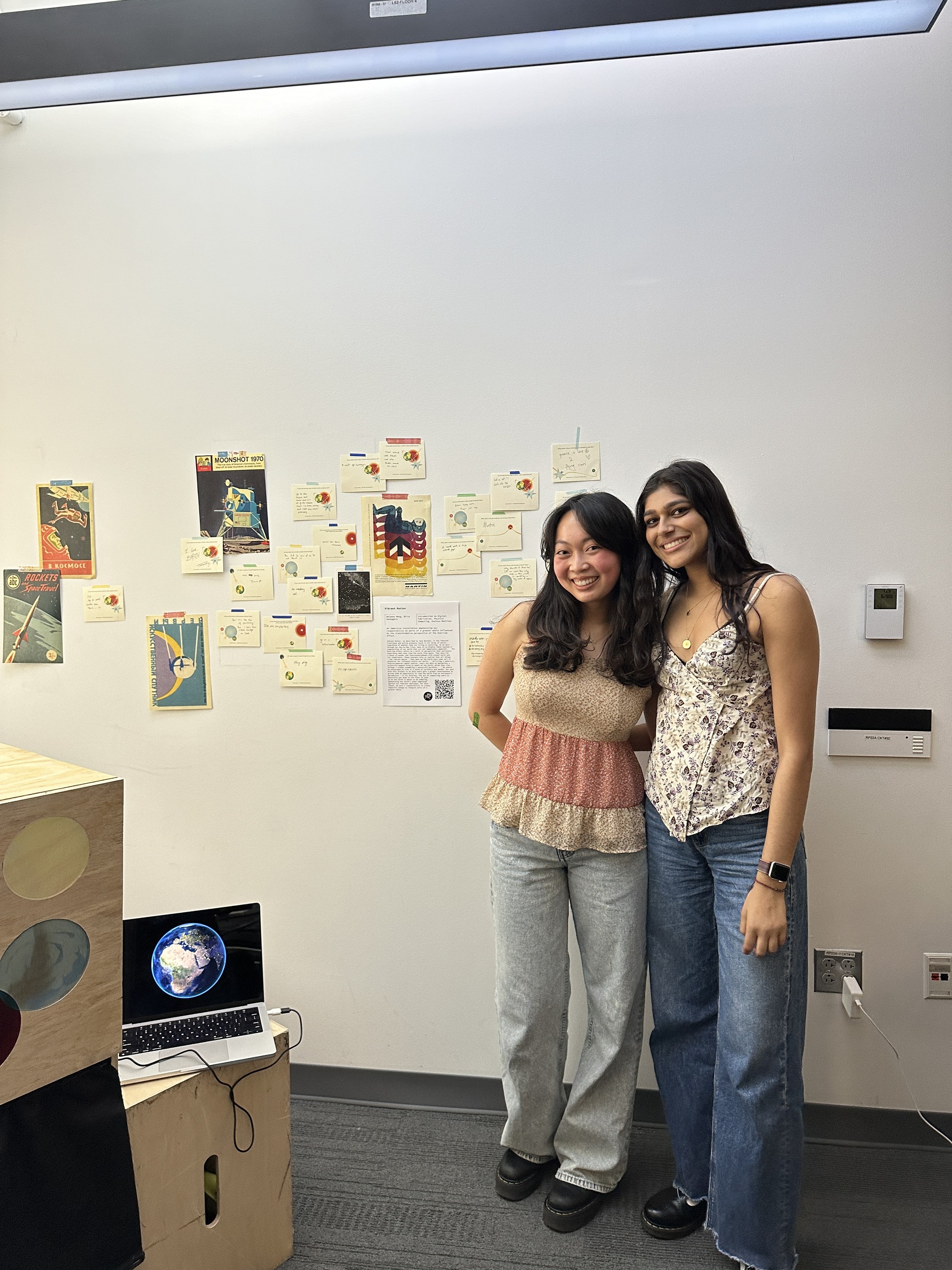
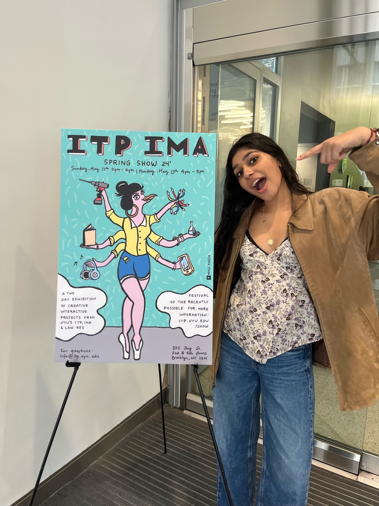
User interaction revolving around the ability to view the Earth in its entirety using a handheld controller offered an interesting juxtaposition to the realization of our own inherent smallness compared to the planet's magnitude that is so often described by those who experience The Overview Effect — the opportunity to control a planet using a miniature globe feels, interestingly enough, innately powerful. To us, however, this dissociation only emphasizes each of our own potentials for impact within our communities and in our world. Therefore, we began ideating our space machine around this core interaction with the idea of placing the user in the perspective of an astronaut experiencing The Overview Effect. Delaney and I presented our Vibrant Matter spaceship at the ITP Spring Show 2024. We were met with guests of all ages who played with or examined our work. Their electrifying reactions to our work were more than rewarding. But, the real pleasure was engaging in conversation about our work and reading their responses to our discussion questions. Take a look!
